Daktronics G-1000-34-R User Manual
Page 32
Maintenance &
Troubleshooting
4-5
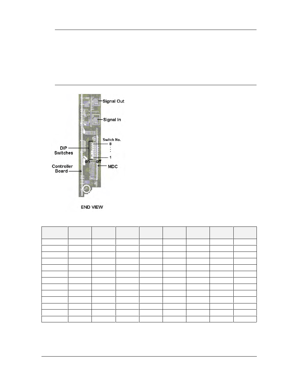
Figure 12: Location of DIP Switches
4.6.2
LED’s and Jumpers
The controller board contains three (3) DIM, one (1) Power, one (1) RUN, and one (1)
Receive Data LED’s. They are located as shown in Figure 11.
The controller’s communication module contains a jumper for a modem system. The
jumper must jump both pins for a modem system. For all other applications, the jumper
must be removed.
4.6.3
Controller Address and Test Mode
Before a display can be run in a sign network, it must have an
“address.” The display address can be set by the use of “DIP”
switches located on a PC board known as the MDC. The MDC
is the circuit card mounted in the lower right corner of the
controller board (as seen in Figure 11).
Locate the DIP switches on the MDC. They should be on the
bottom end of the card (if it is oriented as shown in Figure 11).
Refer to Figure 12 for a picture of the DIP switches.
When replacing a controller board, be sure to set the DIP
switches in the same address configuration as the defective
controller.
Note: A test mode can be activated by setting the DIP
switches to address 0 (flip all the switches toward the numbers
on the circuit board). The display’s power must be downed,
then reconnected to run the test mode.
Address
Switch
Switch
Switch
Switch
Switch
Switch
Switch
Switch
1
2
3
4
5
6
7
8
1
ON
OFF
OFF
OFF
OFF
OFF
OFF
OFF
2
OFF
ON
OFF
OFF
OFF
OFF
OFF
OFF
3
ON
ON
OFF
OFF
OFF
OFF
OFF
OFF
4
OFF
OFF
ON
OFF
OFF
OFF
OFF
OFF
5
ON
OFF
ON
OFF
OFF
OFF
OFF
OFF
6
OFF
ON
ON
OFF
OFF
OFF
OFF
OFF
7
ON
ON
ON
OFF
OFF
OFF
OFF
OFF
8
OFF
OFF
OFF
ON
OFF
OFF
OFF
OFF
9
ON
OFF
OFF
ON
OFF
OFF
OFF
OFF
10
OFF
ON
OFF
ON
OFF
OFF
OFF
OFF
11
ON
ON
OFF
ON
OFF
OFF
OFF
OFF
...
...
...
...
...
...
...
...
...
127
ON
ON
ON
ON
ON
ON
ON
ON