Daktronics G-1000-34-R User Manual
Page 21
Electrical
Installation
3-5
3.5
Signal Termination Between Two (or more) Displays
Reference Drawings:
System Riser Diagram (422) . . . . . . . . . . . . . . . . Drawing A-88425
System Riser Diagram (Modem) . . . . . . . . . . . . . Drawing A-88426
Signal/Power Termination Panel . . . . . . . . . . . . . Drawing A-88427
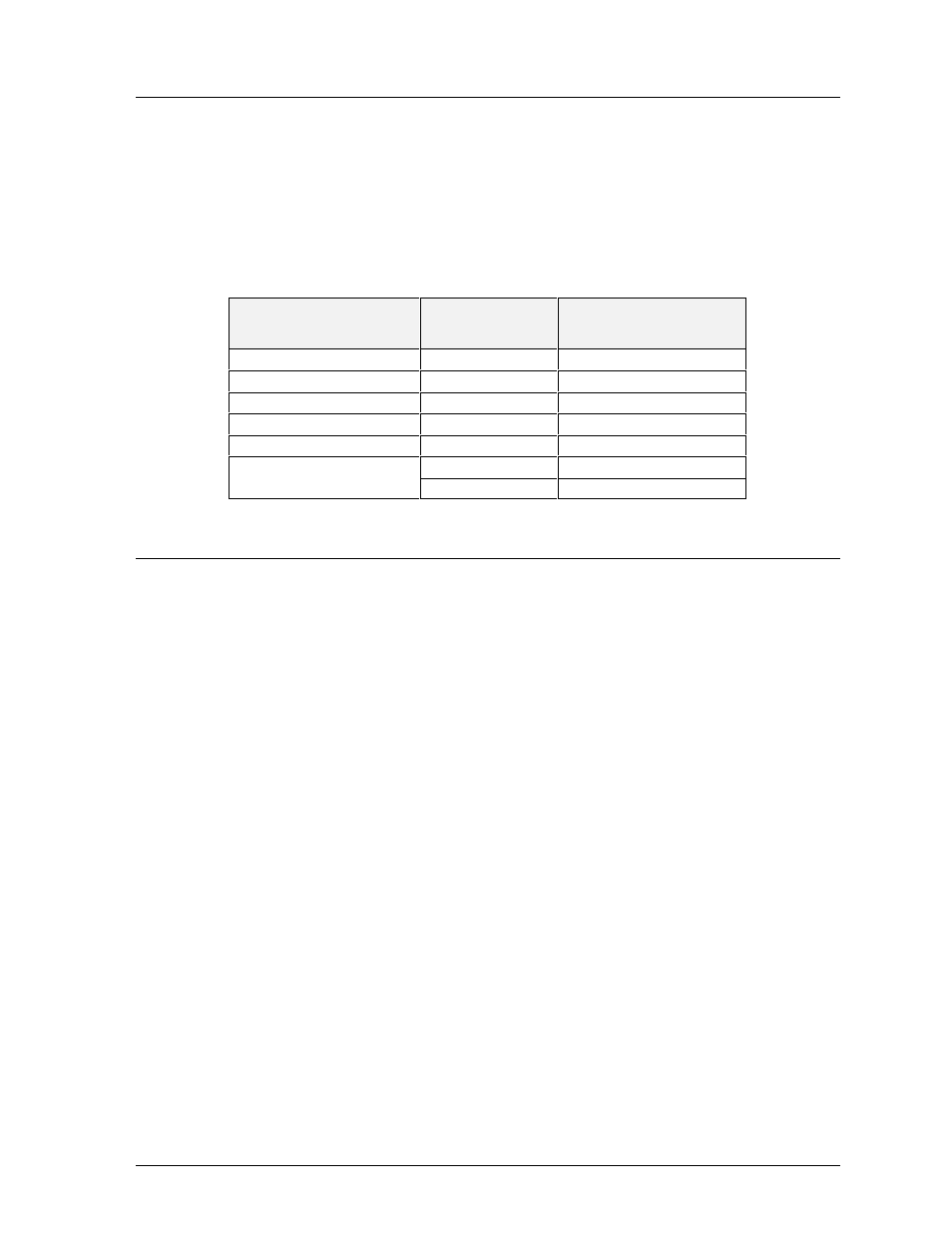
This is the most common method of terminating signal between two or more signs. A 6-conductor
cable is used and one end terminates at the “DATA OUT” 10 position terminal block (TB43) on the
first display. The other end terminates at the “DATA IN” 10 position terminal block (TB42) in the
second display.
Sign A
Sign B
Data Out (TB43)
Field Cabling
Data In (TB42)
Pin 1 (GND)
Green
Pin 6 (GND)
Pin 2 (Data TX-N)
Blue
Pin 5 (Data RX-N)
Pin 3 (Data TX-P)
White
Pin 4 (Data RX-P)
Pin 4 (Data RX-N)
Brown
Pin 3 (Data TX-N)
Pin 5 (Data RX-P)
Black
Pin 2 (Data TX-P)
Pin 6 (GND)
Red
Pin 1 (GND)
Shield (Bare)
N.C.
3.6
First Time Turn On
When first powered up, the display will run through an initialization in which it will display the
following:
1.
Output Test (DDD’s)
2.
Display Model Number (i.e. G-1000-3-6x96)
3.
Firmware Version
4.
COM1 Configuration (Typically V1500)
5.
COM2 Configuration (Either DataView or RTD)
™
6.
Power Line Frequency (i.e. 60 Hz)
7.
Display Address
8.
Sign Name
9.
Modem (if present)