Daktronics G-1000-34-R User Manual
Page 30
Maintenance &
Troubleshooting
4-3
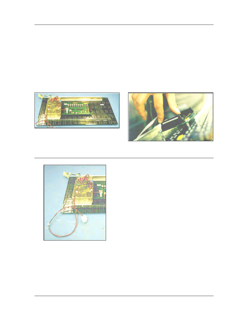
Figure 9: Removing the signal connections
Figure 8: Rear View; Display Module
Figure 10: Module Power Supply
4.4
LED Driver Replacement
The LED driver is located on the rear side of the module (refer to Figure 8).
1.
Remove all power and signal connections from the board. The connectors can be released
by squeezing together the locking tabs, then gently pulling the connector free (refer to
Figure 9).
2.
Remove the four corner #6 screws.
3.
Take note of the driver’s orientation.
4.
Carefully remove the driver from the display board. Use an even force to prevent any
damage due to bending of the connector pins on the display board.
Reverse the above steps to replace the driver.
4.5
Power Supply
The power supply is mounted on the back of every other
module. The first power supply is located behind module
A*02 (* is the number of the line. Refer to Section 4.2).
This unit supplies power to modules A*01 and A*02. The
remaining power supplies are located behind A*03, A*05,
A*07 and A*09. The power supplies connect to the module
they are located behind and the one to the right of it (as seen
from the front view). This pattern is consistent for each line.
Refer to Section 4.3 for information on removing a module.
Once the module has been removed from the display:
1.
Remove the ground wire from the ground nut.
2.
Unplug the two power wires.
3.
Place the module face down on a soft, flat
surface.
4.
Remove the power module by removing the single
screw on the bottom L-bracket.
5. Pull and slide out the power module.
Follow the above steps in reverse order to install a new power supply.