Daktronics G-1000-34-R User Manual
Page 20
Electrical
Installation
3-4
J-Box
Field Cabling
Terminal Block (Data In)
Pin 1 (N.C.)
Pin 2 (N.C.)
Pin 2 (RX-P)
Clear
Pin 3 (TX-P)
Pin 3 (GND)
Shield
Pin 4 (GND)
Pin 1 (TX-P)
Black
Pin 5 (RX-P)
Pin 6 (N.C.)
3.4.2
RS/422
Reference Drawings:
Signal/Power Termination Panel . . . . . . Drawing A-88427
System Riser Diagram (422) . . . . . . . . . Drawing A-92681
One end of the signal cable should be terminated to the 10 position terminal block in the display
labeled “DATA IN” (TB42). Drawing A-88427 is an example of the termination panels. The
other end is terminated at the signal converter (Daktronics part number 0A-1127-0237) in the
control room.
Signal Converter (J4/J5)
Field Cabling
Terminal Block (Data In)
Pin 1 (GND)
Red
Pin 1 (GND)
Pin 2 (RX-P)
Black
Pin 2 (TX-P)
Pin 3 (RX-N)
Brown
Pin 3 (TX-N)
Pin 4 (TX-P)
White
Pin 4 (RX-P)
Pin 5 (TX-N)
Blue
Pin 5 (RX-N)
Pin 6 (GND)
Green
Pin 6 (GND)
Shield (Bare)
N.C.
3.4.3
Modem
Reference Drawings:
System Riser Diagram (Modem) . . . . . Drawing A-88426
Signal/Power Termination Panel . . . . . Drawing A-88427
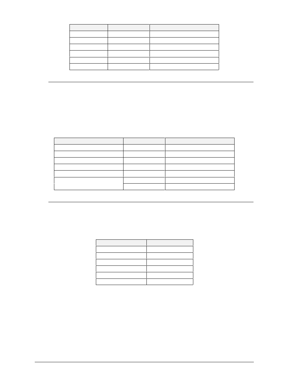
Terminate the signal telephone wires in TB42 as follows:
Telephone Wires
Terminal Block
N.C.
Pin 1
N.C.
Pin 2
TIP-P
Pin 3
Ring-P
Pin 4
N.C.
Pin 5
N.C.
Pin 6
- TI-3031 4-Inch LED Bar-Digit Locker Room Clock (22 pages)
- ST-2005 Backlit & Non-Backlit Scorer’s Tables (24 pages)
- BB-2135 Backboard LED Light Strip (36 pages)
- TN-2563 Tuff Sport Indoor Multi-Court Tennis LED Scoreboard (112 pages)
- BB-2144 Tuff Sport Basketball LED Scoreboard (184 pages)
- TN-2607 Single-Court Outdoor LED Tennis Scoreboard (134 pages)
- CR-2004 Multi-Section Cricket Scoreboard (90 pages)
- FT-7150 Touchpad (29 pages)
- SW-2008 Aquatics/Track LED Scoreboard (84 pages)
- SO-1424-11 Multi-Section Outdoor LED Scoreboard (158 pages)
- FB-4005-31 DistaView Outdoor LED Scoreboard (64 pages)
- MS-2018 Generation III Stackable LED Scoreboard (76 pages)
- GM-2103 LED Gymnastics Scoreboards (38 pages)
- HS-200 Horn Start (36 pages)
- Indoor Hockey Goal Lights (44 pages)
- LED End-of-Period Basketball Lighting (34 pages)
- MS-2013 Portable LED Scoreboard (52 pages)
- WR-2106 Matside Jr. LED Wrestling Scoreboard (44 pages)
- TI-2021 Multipurpose Track & Field LED Timing Display (50 pages)
- P1647 Multi-Section Outdoor LED Scoreboard (52 pages)
- P1647 Multi-Section Outdoor LED Scoreboard (50 pages)
- DA-1200 Outdoor Decorative Accent (30 pages)
- 2000 Rodeo OmniSport (72 pages)
- Outdoor LED Scoreboards Installation (58 pages)
- Outdoor LED Scoreboards Service Manual (52 pages)
- SO-2014 Generation IV Multi-Section Outdoor LED Scoreboard (208 pages)
- P1647 Multi-Section Outdoor LED Scoreboard (44 pages)
- PC-2001 Pace Clock System (40 pages)
- PC-2002 Pace Clock System (32 pages)
- BB-314 Portable LED Basketball Scoreboard (28 pages)
- Protective Screen (4 pages)
- TI-2002 Portable LED Timer (32 pages)
- Radar Gun Speed of Pitch Interface (27 pages)
- TI-2026 Segment Timer (28 pages)
- Single-Section Outdoor LED Scoreboards (46 pages)
- LED Aquatics/Track Displays SW-2000 Series 10 Numeric Digit (86 pages)
- TI-2022 Portable LED Timer (32 pages)
- Single Section DistaView Outdoor LED Scoreboards Generation IV (99 pages)
- BB-2151 (NBA only) Transparent Shot Clock (48 pages)
- TN-2563 Tuff Sport Indoor LED Tennis Scoreboard (34 pages)
- Scoreboard Trumpet Horn (50 pages)
- ST-3001 Tuff Sport & ColorSmart LED Scorer’s Table (48 pages)
- Tuff Sport & ColorSmart Indoor LED Scoreboards (46 pages)
- Tuff Sport Indoor LED Scoreboards (40 pages)
- Tuff Sport& ColorSmart FourSided Indoor LED Scoreboards (58 pages)