Section 4: maintenance & troubleshooting – Daktronics G-1000-34-R User Manual
Page 28
Maintenance &
Troubleshooting
4-1
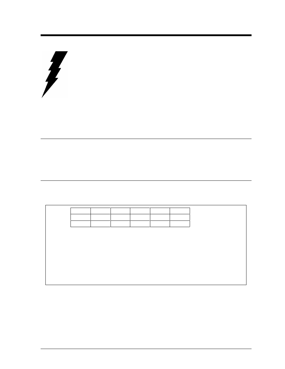
A101
A102
A103
A104
A105
A106
Line 1
A201
A202
A203
A204
A205
A206
Line 2
A301
A302
A303
A304
A305
A306
Line 3
1.
Labeling reference begins with the upper left module and increments to the right and down
from that point, independent of the display size.
2.
Modules are designated by the prefix “A”. A101 represents the upper left module.
3.
The hundreds digit indicates the display line number. A101 through A106 make up the first
display line, A201 through A206 make up the second display line and so forth.
Figure 3: Module Identification Numbering Convention
Section 4: Maintenance & Troubleshooting
IMPORTANT NOTES:
1. Disconnect power before any repair or maintenance work is done
on the display!
2. Any access to internal display electronics must be made by
qualified service personnel.
3. The Daktronics product manager’s engineering staff must approve
any changes that may affect the weather tightness of the display.
This includes, but is not limited to, the border shrouding and back
sheets. If ANY modifications are made to the weather tightness of
the display, detailed drawings of the changes MUST BE submitted
to our engineering staff for evaluation and approval or the
warranty will be null and void.
4. Care must be taken when handling the display’s face panel to
prevent any injuries or damage, especially in windy conditions.
4.1
Weather Stripping
To ensure that the display is waterproof, weather stripping has been provided around the entire
display and around the individual lines. It is important that the weather stripping is installed
properly at all times or water may leak into the display and damage components.
4.2
Module Numbering Convention
Figure 3 shows the module numbering convention. A module is six pixels high by sixteen pixels wide,
with the driver board attached. A, B and C designate modules for each face on a multiple face display.