Daktronics G-1000-34-R User Manual
Page 41
Appendix B
B-1
Appendix B: G-1000 Design Prior to
November 1, 1996
Daktronics is continually making improvements to our display technologies to offer the highest quality and
latest technology in our products. The following items have been changed in the manual to reflect the
newest design. If your G-1000 display was manufactured prior to November 1, 1996, please follow
the manual except for the items listed in Appendix B.
Display Changes:
C Cabinet dimensions, refer to Drawing B-78565.
C Face panel dimensions, refer to Drawing A-88101.
C Light detector location, refer to Drawing B-78102.
C Entrance enclosure layout, refer to Drawing A-76570.
C Entrance enclosure location, refer to Drawing B-78565.
C Light detector wiring as below.
C Temperature sensor wiring as below.
Termination Panel . . . . . . . . . . . . . . . . . . . . . . . . . . . . . . . . . . . . . . . . . . . . . . . . Drawing A-76570
Face panel Replacement . . . . . . . . . . . . . . . . . . . . . . . . . . . . . . . . . . . . . . . . . . Drawing A-88101
Mechanical Layout . . . . . . . . . . . . . . . . . . . . . . . . . . . . . . . . . . . . . . . . . . . . . . . Drawing B-78565
Wiring Schematic . . . . . . . . . . . . . . . . . . . . . . . . . . . . . . . . . . . . . . . . . . . . . . . . Drawing B-78102
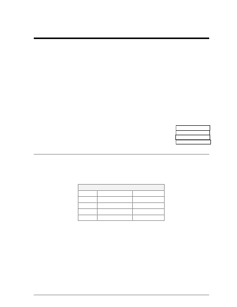
Light Detector
The light detector must be mounted near the display so that the light detector is facing the same
direction as the face of the display. A 4-conductor cable is used to connect this light detector to
the display. The cable is terminated on the controller board on the terminal block labeled “TB2.”
Refer to Drawing A-76570.
Terminal Block In
Pin 1
Red
(Photo +5V)
Pin 2
Black
(Photo GND)
Pin 2
Bare
N/A
Pin 3
Green
(Photo RX-P)
Pin 4
White
(Photo RX-N)
Note: If the display is two sided, each side has its own light detector.