Daktronics nomenclature, Daktronics nomenclature -5, Figure 2: positions-1648 display -5 – Daktronics CE-1010 User Manual
Page 9: 5 daktronics nomenclature
1.5 Daktronics
Nomenclature
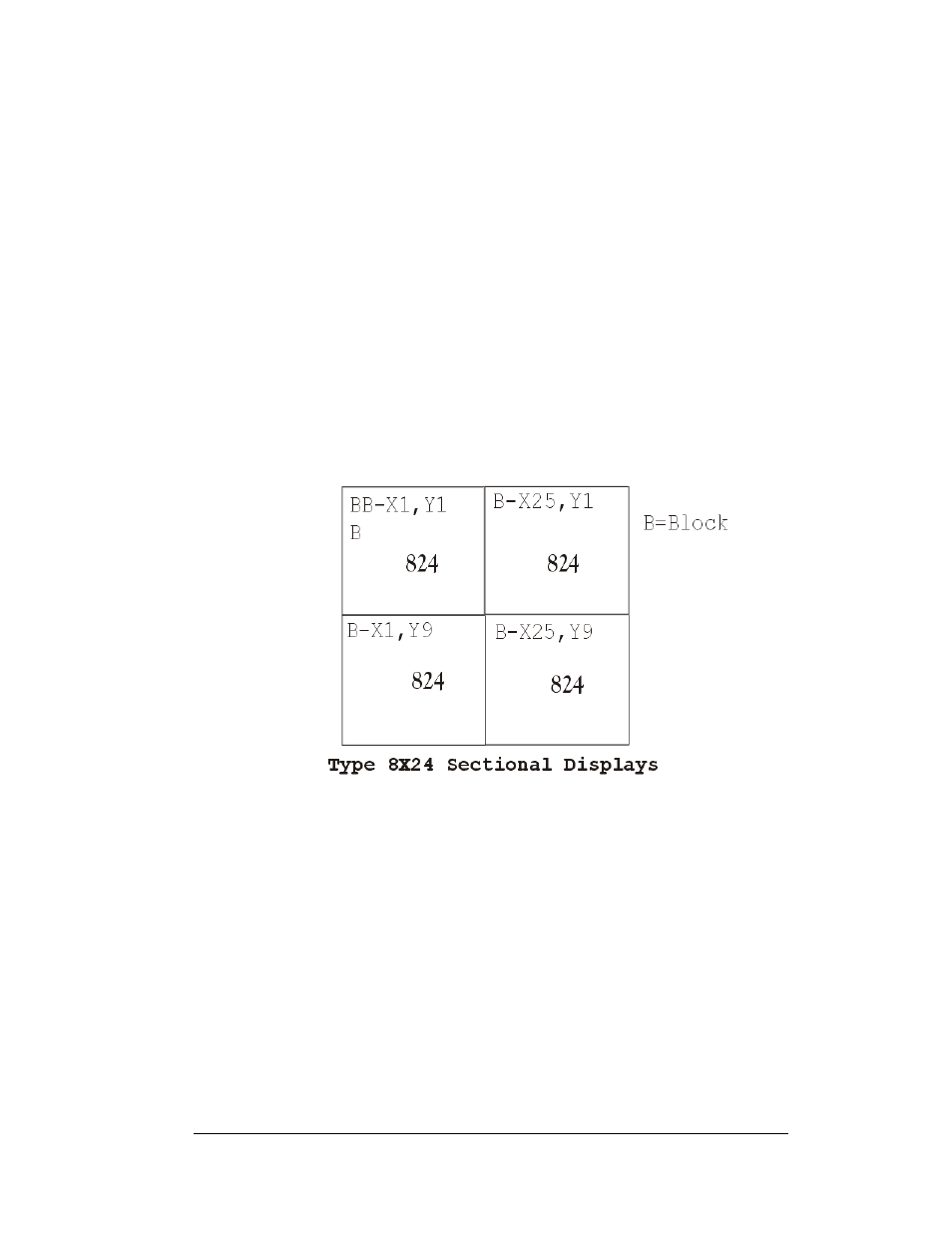
The X-coordinate refers to the LED block placement within a row of characters. To
count the placement of the X-coordinate, begin with the left-most LED block as X=1
and continue counting across through the entire display to the right-most LED block.
The Y-coordinate refers to the LED block placement within a column of characters.
To count the placement of the Y-coordinate, begin with the upper-most LED block
as Y=1 and continue counting down through the entire display to the bottom-most
LED block. The software on the control PC uses these coordinates to determine the
placement of data within the larger display.
The X,Y coordinates at the upper left character of each section need to be configured
for proper display orientation.
Figure 2: Positions-1648 Display
In addition, various Daktronics drawings may contain the following labeling
formats:
•
“TB_ _” shows a termination block for power or signal cable.
•
“F_ _” denotes a fuse.
•
“E_ _” signifies a grounding point.
•
“J_ _” stands for a power or signal jack.
•
“P_ _” represents a power or signal plug for the opposite jack.
Finally, drawings commonly have Daktronics part numbers. You can use those part
numbers when requesting replacement parts from Daktronics Customer Service.
Take note of the following part number formats:
•
“0P-_ _ _ _-_ _ _ _” gives the form of an individual circuit board, such as a
module driver.
Introduction
1-5