Display controller, Display controller -5, Figure 17: mdc controller -5 – Daktronics CE-1010 User Manual
Page 23
Display Controller
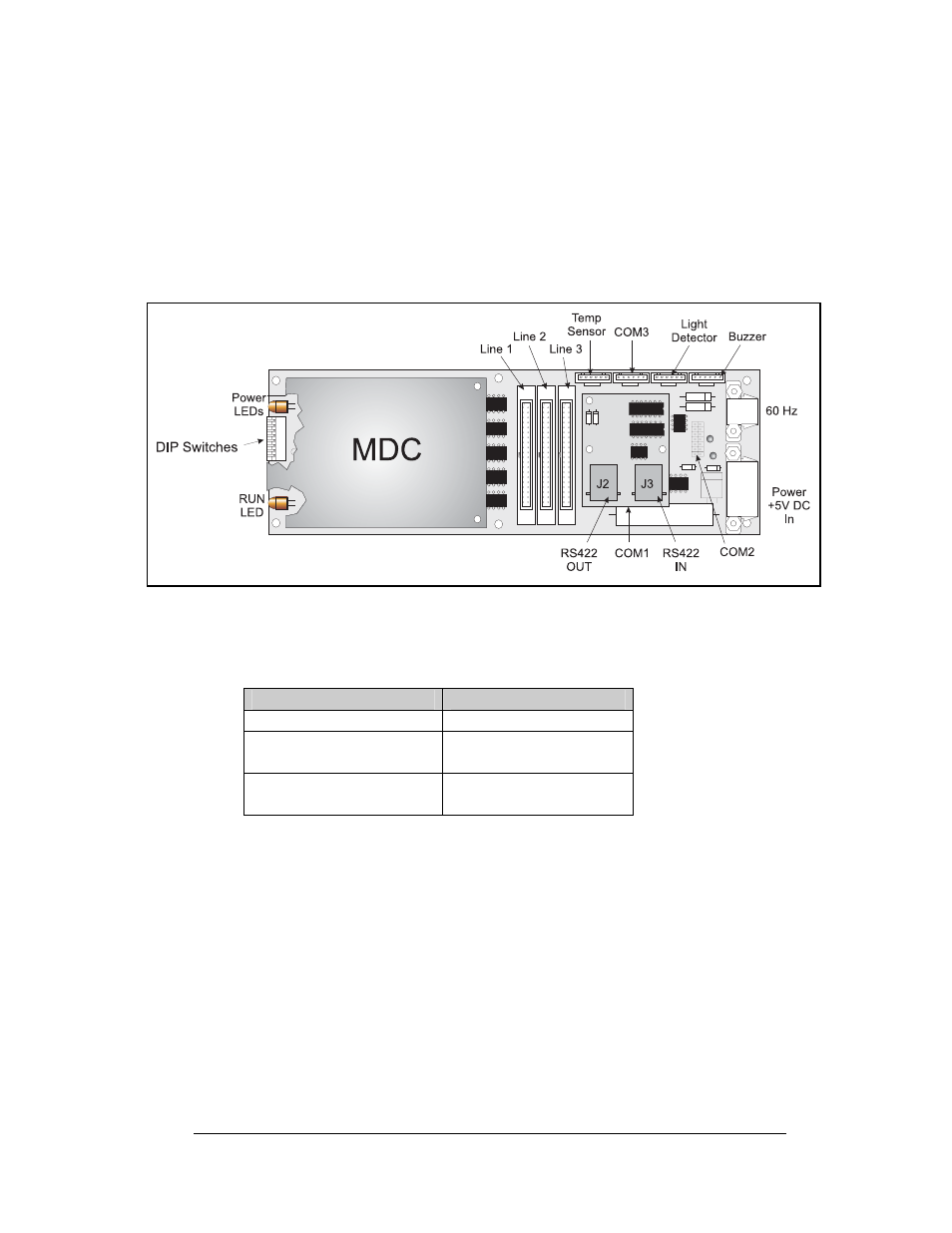
The display controller is mounted to the inside rear of the display cabinet. Refer to
Figure 17 for an illustration of the controller and the appropriate schematic for its
location in the display. The controller receives information from the computer, interprets
it, and activates the appropriate LEDs on the display. The display controller also has a set
of eight switches by which an address can be set using standard binary code (refer to
Section 4.3).
Figure 17: MDC Controller
Under normal operation, the normal state of the controller’s status indicator LEDs is as
follows:
Status Indicator
Normal State
MDC Power LED
On Constant
Product Board Power
LED
On Constant
Run LED
Flashes once per
second
To replace a failed controller:
1. Remove the module panels as described in Section 4.1. Each display section has
one controller mounted inside it. Refer to the appropriate schematic for the
controller location.
2. Disconnect the power cable and signal ribbon cables. Release the power cable
by squeezing the tabs on each side of the connector. Release the signal ribbon
cables by spreading the clasps on the jack and gently pulling up on the ribbon
cable. Take note of the signal cables and their appropriate jacks.
3. Remove all #6 connecting screws and the controller will be free. If the address
switches are used, take note of the switch configuration and set the same address
on the new controller.
4. To install a new controller, reverse the previous procedure.
Maintenance and Troubleshooting
4-5