Accessing the interior of the display, Accessing the interior of the display -2, Figure 9: screw locations -2 – Daktronics CE-1010 User Manual
Page 20: Figure 11: module panel removal -2, 1 accessing the interior of the display
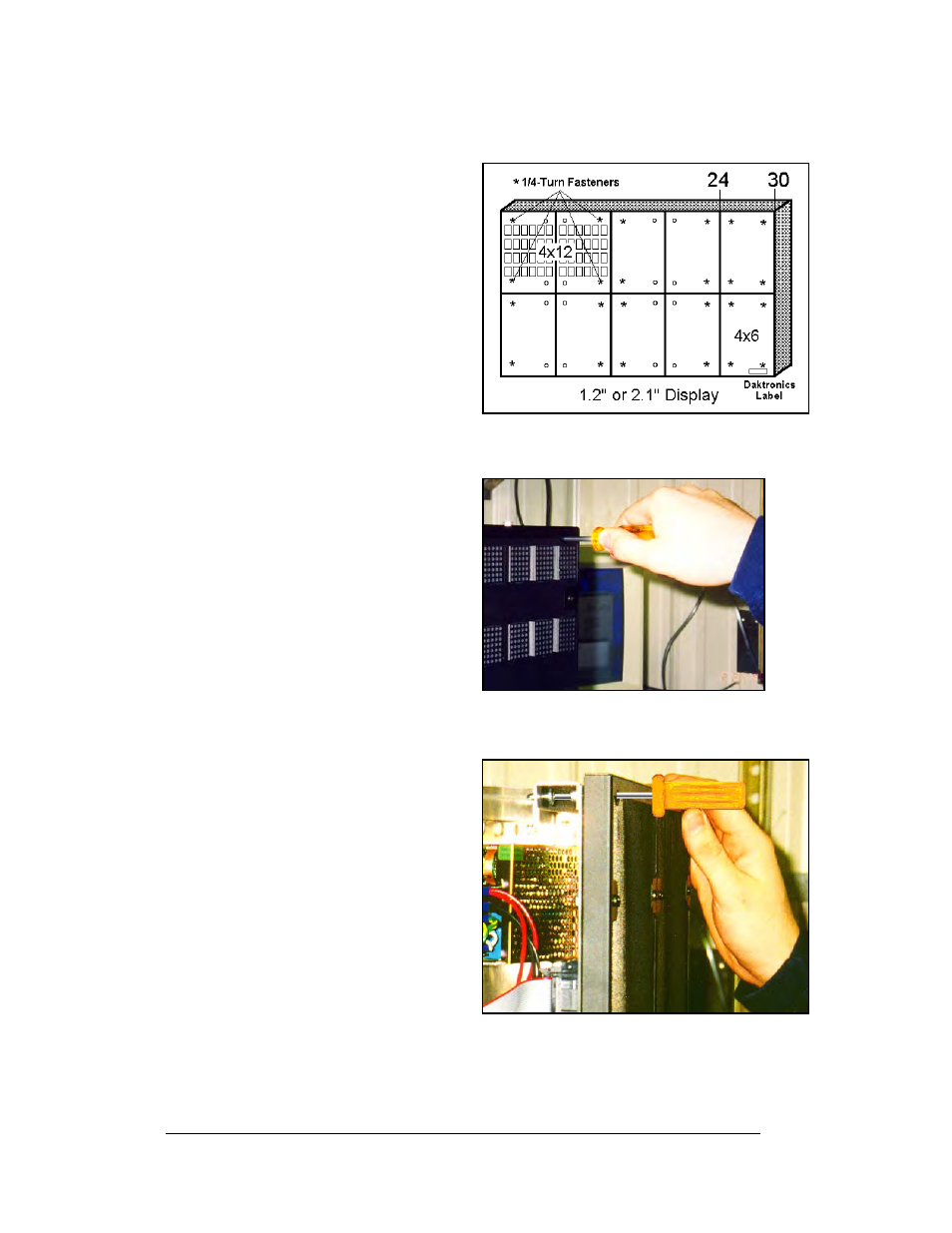
4.1 Accessing the Interior of the Display
Depending on the overall size of a
display system, sectional displays may
have two sizes of front access
removable panels. Finding the
Daktronics labels on the front of the
display will help in locating the lower
right corner of a display section.
Figure 9: Screw Locations
For 1.2" and 2.1" display types, the
module in this corner may either be a
4x6 or 4x12 panel. For 3.2" and 4.2"
displays, the modules are all 2x6
panels. Panels are removed by
accessing ¼-turn fasteners in the
corners of a module panel.
Figure 10: Locating module panel ¼-turn fasteners
Note: Not every hole has a ¼-turn
fastener. Only the four corner holes of
the module panel do. Refer to Figure
9.
The screwdriver must pass through the
face panel. The ¼-turn screws are
located behind the face panel.
Using a #1 Philips screwdriver, turn
the 4 ¼-turn screws securing the LED
module panel to the cabinet of the
display one-quarter turn counter-
clockwise. Refer to Figure 9 and
Figure 10. The screws are designed to
remain in the LED module flanges,
but release from the cabinet.
Figure 11: Module Panel Removal
Gently pull the LED module panel
from the body of the display. It will
come forward as a complete unit.
Refer to Figure 9 and Figure 10.
Note: Use caution when removing the
LED module panel. The power wires
and ribbon cable connecting the LEDs
to the inside of the display will still be
connected. Take care not to scratch the
modules wire cloth filter.
Maintenance and Troubleshooting
4-2