Power supply replacement, Power supply replacement -4, Figure 15: power supply -4 – Daktronics CE-1010 User Manual
Page 22: Figure 16: power supply cable connections -4
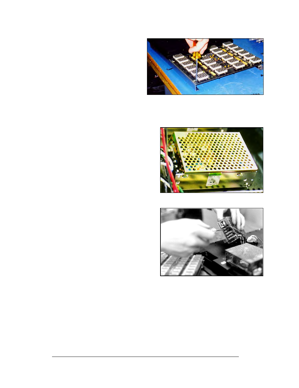
5. Remove the screws located along
the top and bottom edge of the
module, and lift the PC board off of
the rails. Refer to Figure 14.
Figure 14: Removing Top and Bottom Module
Screws
6. Reverse the previous procedure to
attach a new module.
Power Supply Replacement
1.2" and 2.1" Power to the LED modules is
provided by small 5V power supplies. Each
power supply can support two 4x6 modules.
The controller board also requires a 5V power
supply. The power supplies are mounted to the
back sheet within the display cabinet.
Figure 15: Power Supply
3.2" and 4.2" Power to the LED modules is
provided by 6.5V power supplies. Each power
supply can support two 2x6 modules. The
controller board also requires a 5V power
supply.
Maintenance and Troubleshooting
4-4
To remove a power supply that has failed, first
remove the LED module in front of the failed
power supply as described in Section 4.1.
Each power supply is attached to a power
supply plate by two metric screws. The plate is
secured to the back sheet by two (2) #6 hex
head screws. Refer to Figure 15. Use a
3
/
16
-nut
driver to remove the #6 hex head screws.
Lift the power supply and plate back. The
metric screws securing the power supply to the
plate are now accessible. Use a #1 Philips head screwdriver to remove the screws and
free the power supply.
Figure 16: Power Supply Cable Connections
Disconnect the power cables as shown in Figure 16. The power supply is now fully
released and ready for replacement. Follow the previous steps in reverse order to reattach
the new power supply. Refer to the display’s schematic for the proper wiring
configuration.