Rs422 system, Sign to sign/section to section connections, Rs422 system -3 – Daktronics CE-1010 User Manual
Page 17: Sign to sign/section to section connections -3, Figure 8: output signal cable connection -3, 3 rs422 system
3.3 RS422
System
A RS422 system requires a signal converter to connect the first sign to the computer.
1.
Plug the serial cable’s 25-pin connector into the signal converter.
2.
Plug either the 9-pin or the 25-pin connector (depending on your PC) into
the RS232 COM port to be used.
3.
Plug the signal converter’s power cord into a 120 VAC grounded outlet.
4.
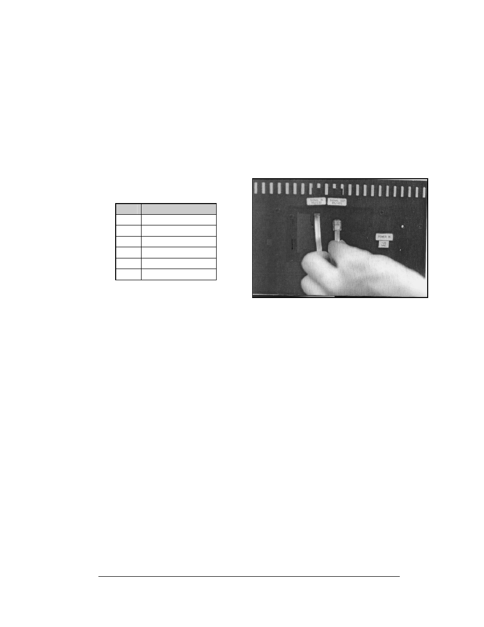
Plug a flipped phone cable into the “RS422 OUT” of the signal converter
and the opposite end into the “RS422 IN” of the first display.
The “RS422 IN” jack’s pin out is as
follows:
Figure 8: Output Signal Cable Connection
Pin
Function
1 N.C.
2 D1OUT-P
3 D1OUT-N
4 D1IN-P
5 D1IN-N
6 N.C.
3.4 Sign to Sign/Section to Section Connections
When wiring the sign to sign network, the cable and connectors discussed earlier in
this section are used. Pay special attention to the information regarding flipped
cables to help ensure a successful installation. The best method of wiring the signs
together is to start at the first sign, as it is designated to begin the network.
1.
Plug the cable into the “SIGNAL OUT” output jack of the first sign (refer
to Figure 8) and the other end of the cable into the input jack of the next
sign.
2.
Continue this procedure throughout the network. When the wiring is
complete, the last sign will have nothing in the output jack.
3.
Before hanging the displays, review Section 2.4.
Electrical Installation
3-3