Direct – indoor connection – Daktronics DataTime Outdoor LED Time & Temperature Displays User Manual
Page 18
5. Mount the temperature sensor as described in Section 2.4, and connect the quick
connect cable to the four-pin quick connect on the back of the display.
6. The DataMaster controller plugs into the J-box using a DB9M to DB9F serial cable.
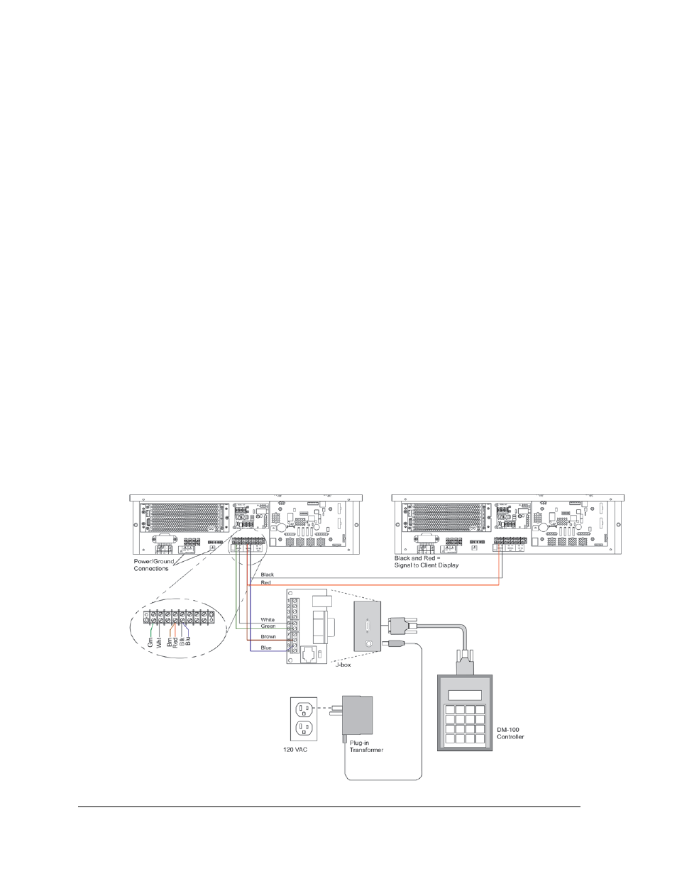
Direct – Indoor Connection
Reference Drawings:
Riser Diagram, Indoor Wire Control ...................................................... Drawing A-175342
Time & Temp Power/Signal Hookup ..................................................... Drawing A-938369
Enclosed Driver, 4 Column .................................................................... Drawing A-938300
A direct-controlled display can also be used from a J-box at in indoor location. In that case,
only two, 22 AWG, signal wires will need to be connected to the J-box and a wall pack
transformer will be used for power to the DataMaster controller. The distance from the
indoor J-box to the host driver can be up to 2,000 ft (600 m). Refer to Figure 10 and Drawing
A-175342 for system layout and signal connections.
1. Mount the J-box at an indoor location.
2. Select the host driver by inserting the Protocol-4 plug into the five-pin protocol jack
(J20).
3. Route a four-conductor, 18 AWG, shielded signal cable through conduit from the J-
box to the driver enclosure in the host display.
4. Connect the signal wire, through conduit, from the J-box to the driver enclosure as
shown in Figure 10 and listed in the table. Refer to Drawings A-938369 and A-938300
for additional information.
Figure 10: Direct Connection from Indoor Location
14
Electrical Installation