Host/client definitions, Direct – outdoor connection – Daktronics DataTime Outdoor LED Time & Temperature Displays User Manual
Page 16
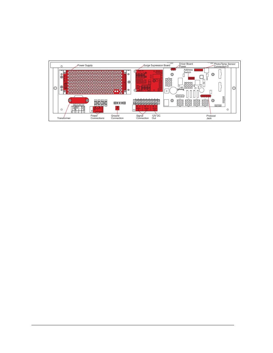
Refer to Drawing A-938300 for a complete review of power and signal connections for direct
connection to the displays. Drawing A-166216 provides connection specifications for the
four-column drivers used in all DataTime time and temperature displays. Power and signal
connections, illustrated in Figure 8, are similar for both drivers.
Host/Client Definitions
Reference Drawings:
Multipurpose 4 Column LED Driver II Specifications............................. Drawing A-166216
Host/Client Definitions ........................................................................... Drawing A-185236
One driver at each display installation is designated as the “host driver.” This driver receives
its signal directly from the DataMaster controller on its “Signal IN” terminals, and it is the
only driver that is connected to the photo/temperature sensor. The “Signal OUT” terminals
on the host are used to connect to the “client driver.”
Select the host driver by inserting the Protocol-4 plug into the five-pin protocol jack (J20).
Refer to Figure 8 or Drawing A-166216 for location of the protocol jack.
With a time and temperature display there is usually only one host and one client. The client
driver receives signal from the host driver, and the client can re-drive this signal to other
drivers.
Direct – Outdoor Connection
Reference Drawings:
Riser Diagram, Outdoor Wire Control ................................................... Drawing A-164988
Time & Temp Power/Signal Hookup ..................................................... Drawing A-938369
Enclosed Driver, 4 Column .................................................................... Drawing A-938300
A direct-controlled display uses a current loop connection from the J-box at the base of the
display to the driver enclosure in the display. All the power and signal wiring terminates at
the driver enclosure. The DataMaster controller receives its power from the display. The
display layout is shown in Drawing A-164988.
Note: The cable from the J-box to the display needs to be routed through conduit or the
display pole to protect it from weather and vandalism.
Figure 8: DataTime Driver Enclosure with 4-Column Driver
12
Electrical Installation