3 lifting the display, 4 temperature and light sensor, Lifting the display – Daktronics DataTime DF-1012 Time & Temperature Display User Manual
Page 8: Temperature and light sensor
4
Mechanical Installation
2.3 Lifting the Display
Hand lift displays into the support structure.
Note: Daktronics assumes no liability for display damage or injury resulting from incorrect setup or incorrect
lifting methods.
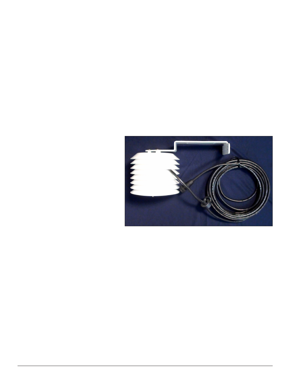
2.4 Temperature and Light Sensor
Reference Drawings:
Time & Temp Power/Signal Hookup .......................................................
Drawing A-938369
Installation, Temp Sensor, G3 .................................................................
Drawing A-184840
Shop Drawings .....................................................................................
Refer to Appendix A
All displays in the DataTime
®
series use a light sensor to regulate dimming functions and a temperature
sensor to collect and display temperature information. Both temperature and light-monitoring electronics are
located in the sensor housing, shown in
The Daktronics Controller Area
Network (CAN) Temperature/Light
Sensor is pre-installed in a protective
housing. The assembly includes the
sensor, mounting bracket, and cabling
with a quick-connect plug. Instructions
that follow describe the placement
and connection of the device. Review
the wiring diagram and connection
illustration in Drawing A-184840 before
beginning.
Dimming involves decreasing overall
display intensity, both for better display
viewing and to prolong LED life. Set the
brightness level highest during the day
to compete with daylight, and lower at night.
Figure 2: Temperature Sensor Housing and Cabling