6 signal connection, Host/client definitions, Signal connection – Daktronics DataTime DF-1012 Time & Temperature Display User Manual
Page 13: Electrical installation 9, Knockouts for, Conduit fittings on the sides of all datatime
Electrical Installation
9
3.6 Signal Connection
Reference Drawings
4 Column MASC Specifications ..............................................................
Drawing A-166216
Time & Temp Power/Signal Hookup .......................................................
Drawing A-938369
Enclosed Driver, 4 Column Reference ....................................................
Drawing A-938300
Route power and signal cables into the display from the side or rear. There are
7
/
8
" knockouts for
1
/
2
" conduit
fittings on the sides of all DataTime
®
cabinets and on the back
panels. All power and signal wiring terminates at the driver
enclosure.
Open the display cabinet by turning the latches on the hinged
doors. To access the driver enclosure, open the access door and
remove the cover. Refer to the Shop Drawings for the access
location for the display.
Refer to Drawing A-938300 for a complete review of power and
signal connections for direct connection to the displays. Drawing
A-166216 provides connection specifications for the four-column
drivers used in all DataTime
®
Time & Temperature displays.
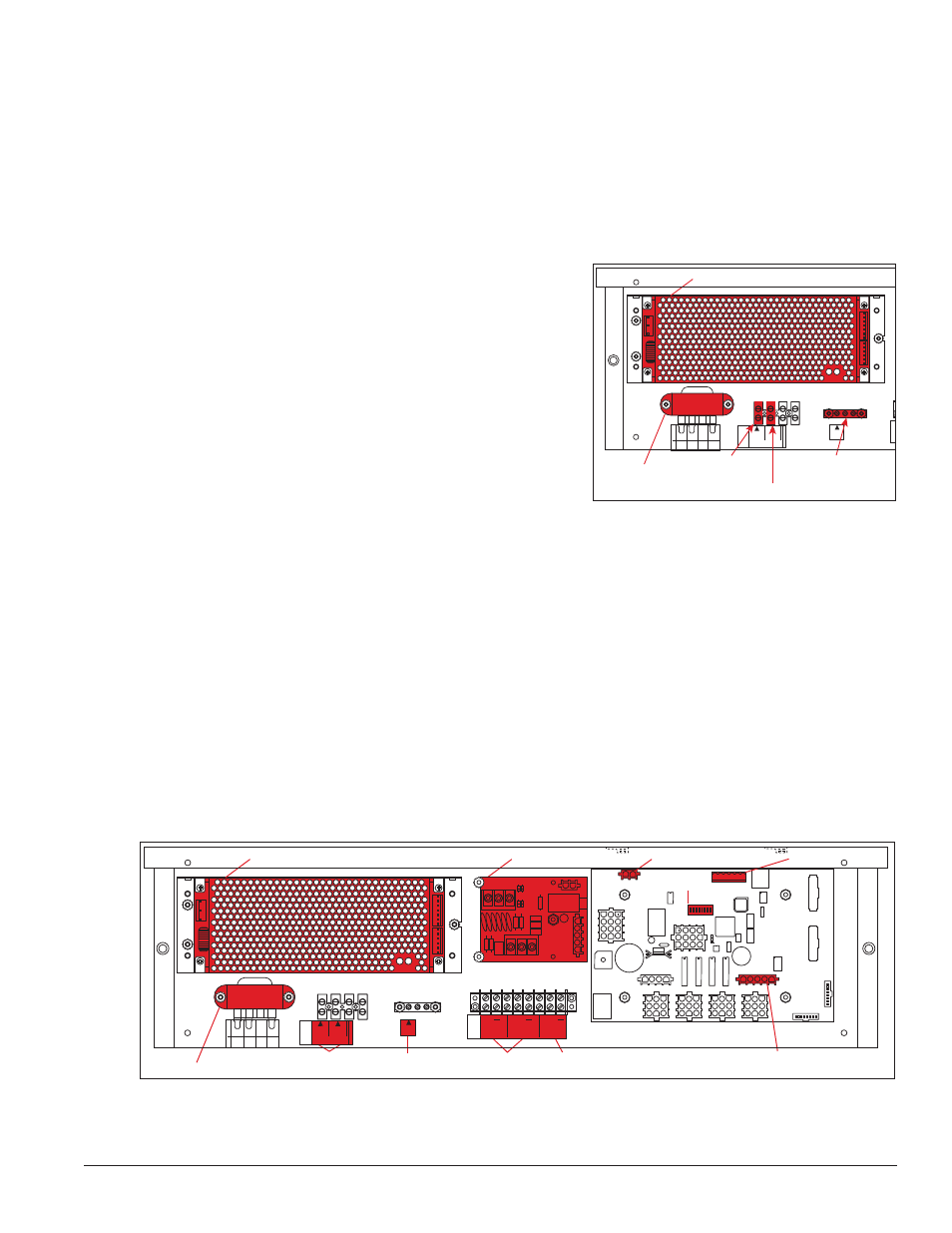
Power and signal connections, illustrated in
Figure 8, are similar
for both drivers.
Host/Client Definitions
Reference Drawings:
Multipurpose 4 Column LED Driver II Specifications ..............................
Drawing A-166216
Host/Client Definitions .............................................................................
Drawing A-185236
One driver at each display installation is designated as the host driver, which receives its signal directly
from the DataMaster controller on its Signal IN terminals. It is the only driver that is connected to the photo/
temperature sensor. The Signal OUT terminals on the host connect to the client driver.
Figure 9 or
Drawing A-166216 for location of the protocol jack.
With a time and temperature display there is usually only one host and one client. The client driver receives
signal from the host driver, and the client can re-drive this signal to other drivers.
0
8 7 6 5
TOP
8 ORG 7 N.C.
6
5 BRN
4
BLK OR SMOOTH
3
2
1
WHT OR GROOVED
TB4
120VAC
LINE
NEUT.
GND
MAIN POWER
Transformer
Connect Earth
Ground Wire
Here
Signal
Connection
12V DC
Out
Power Supply
Surge Supression Board
Driver Board
Power
Photo/Temp Sensor
Connection
Protocol
Jack
Address
Switch
Connect 120V
AC Line Here
Connect
Neutral Here
+
+
+
SIGNAL
IN
TB3
SIGNAL
OUT
12V DC
OUT
SIGNAL OUT
–
+
J1 24VDC
RADIO J2
SHIELD
–
+
SIGNAL IN
Figure 8: Power and Ground Wire Connections
Inside Display
0
8 7 6 5
TOP
8 ORG 7 N.C.
6
5 BRN
4
BLK OR SMOOTH
3
2
1
WHT OR GROOVED
Transformer
Power
Connections
Ground
Connection
Signal
Connection
12V DC
Out
Power Supply
Surge Supression Board
Driver Board
Power
Photo/Temp Sensor
Connection
Protocol
Jack
Address
Switch
TB4
120VAC
LINE
NEUT.
GND
MAIN POWER
+
+
+
SIGNAL
IN
TB3
SIGNAL
OUT
12V DC
OUT
SIGNAL OUT
–
+
J1 24VDC
RADIO J2
SHIELD
–
+
SIGNAL IN
Figure 9: DataTime Driver Enclosure with 4-Column Driver