Red black host display client display, Signal out, J1 24vdc radio j2 shield – Daktronics DataTime DF-1012 Time & Temperature Display User Manual
Page 16: Signal in, Figure 11: direct connection from indoor location, Figure 12: host, signal out to client, signal in
12
Electrical Installation
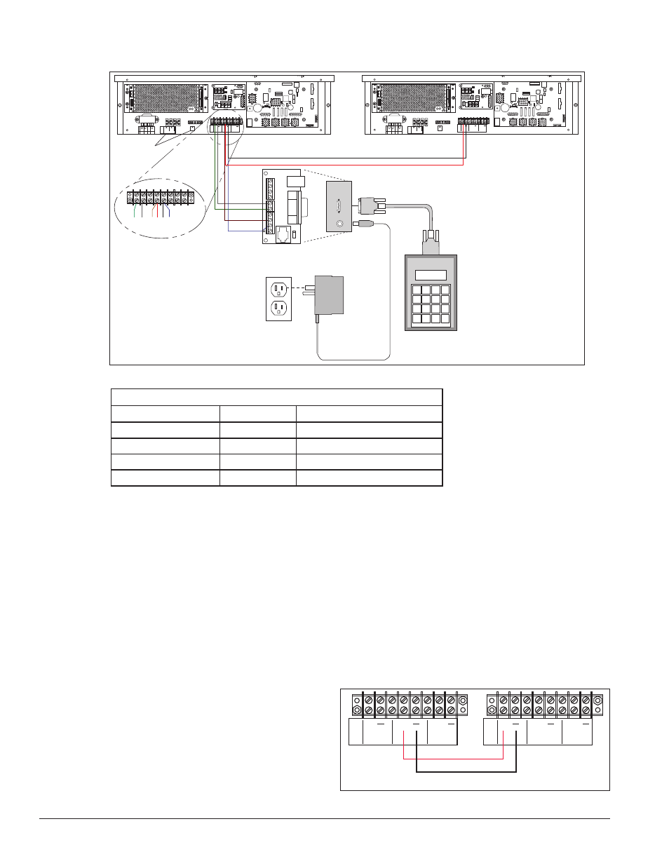
4. Connect the signal wire, through conduit, from the J box to the driver enclosure as shown in Figure
11 and listed in the table. Refer to Drawings A-938369 and A-938300 for additional information.
5. Mount the temperature sensor according to Section 2.4, and connect the quick-connect cable to the
four-pin quick connect on the back of the display.
6. The DataMaster controller plugs into the J box using a DB9M to DB9F serial cable.
7. Plug the wall pack transformer into a wall socket and the other end into the DM-100 controller.
8. Client Definitions and Address Settings
Reference Drawings:
Multipurpose 4 Column LED Driver II Specifications ..............................
Drawing A-166216
Host/Client Definitions .............................................................................
Drawing A-185236
One driver at each display installation is designated
as the host driver, and all other displays are clients.
The Signal OUT terminals on the host are used to
connect to the client drivers. Refer to
Figure 12 and
Drawing A-185236 for an illustration of the client/
host display connection.
Client drivers receive signal from the host driver on
SIGNAL OUT
–
+
J1 24VDC
RADIO J2
SHIELD
–
+
SIGNAL IN
+
+
+
SIGNAL
IN
TB3
SIGNAL
OUT
12V DC
OUT
GND
TB4
120VAC
LINE
NEUT.
MAIN POWER
0
8 7 6 5
TOP
8 ORG 7 N.C.
6
5 BRN
4
BLK OR SMOOTH
3
2
1
WHT OR GROOVED
Black and Red =
Signal to Client Display
DM-100
Controller
Plug-in
Transformer
120 VAC
SIGNAL OUT
–
+
J1 24VDC
RADIO J2
SHIELD
–
+
SIGNAL IN
+
+
+
SIGNAL
IN
TB3
SIGNAL
OUT
12V DC
OUT
GND
TB4
120VAC
LINE
NEUT.
MAIN POWER
0
8 7 6 5
TOP
8 ORG 7 N.C.
6
5 BRN
4
BLK OR SMOOTH
3
2
1
WHT OR GROOVED
Grn
Wht
Red
Brn
Blk Blu
Power/Ground
Connections
Green
White
Brown
Blue
Black
Red
J-box
1
2
3
4
5
6
7
8
9
Figure 11: Direct Connection from Indoor Location
Wiring from Indoor J-Box to Host Driver Enclosure
J-Box Pin Number Cable Color Enclosure Terminal Block
Pin 5
White
Signal IN (-)
Pin 6
Green
Signal IN (+)
Pin 8
Brown
Signal OUT (+)
Pin 9
Blue
Signal OUT (-)
+
+
+
TB3
+
+
+
TB3
Red
Black
Host Display
Client Display
Figure 12: Host, Signal Out to Client, Signal In