Replacing a signal surge board – Daktronics DataTime DF-1012 Time & Temperature Display User Manual
Page 26
22
Parts Replacement
DataTime
®
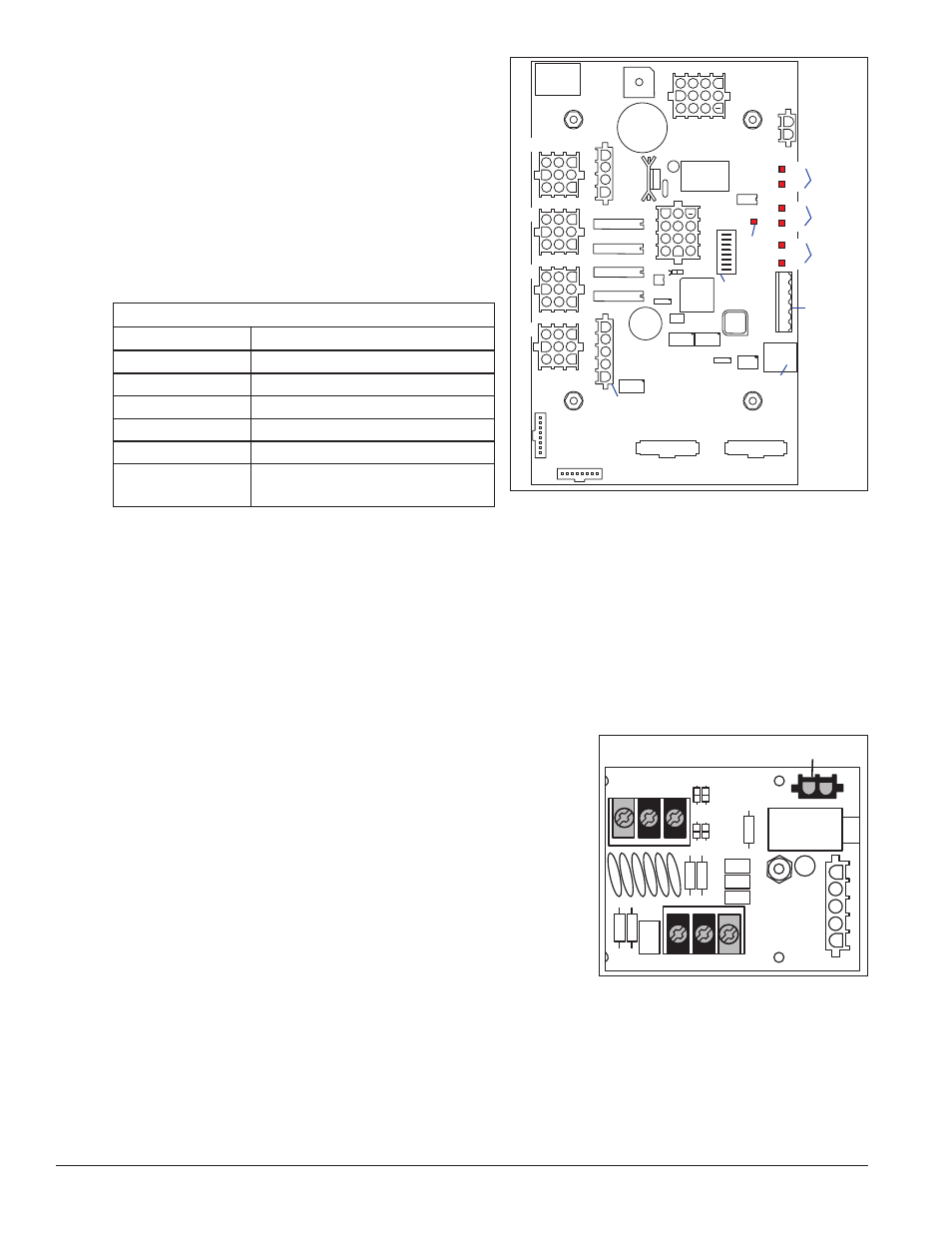
Time & Temp displays use four-column
drivers which have four outputs to digits.
identifies the connector functions. (Major functions are
the same on 16-column drivers.) The table lists the
functions of the various jacks, including those that are
not used in this application.
The display line controlled by the driver is set with an
eight-position DIP-switch that is set before shipping.
Note: Some older drivers use a 12-position address plug
inserted in J19. All DataTime
®
displays ship with a Line
1 address already set.
Replacing a Signal Surge Board
Reference Drawings:
Enclosed Driver, 4 Column Reference ....................................................
Drawing A-938300
Shop Drawings .....................................................................................
Refer to Appendix A
Surge boards are mounted inside the upper-left corner of the driver enclosure inside the display and typically
behind a digit, but location and mounting varies by model. Refer to the Shop Drawings for the location of the
surge board. All DataTime
®
displays are front-accessible.
1. Open the digit panel or display face panel as described in
Section 4.1.
2. Remove the cover from the driver enclosure.
3. Disconnect the power connector from the surge board.
Release it by squeezing together the locking tabs and pull the
connector free.
Note: When reconnecting, remember it is a keyed connector
and will attach in only one way. Do not attempt to force the
connection.
4. Remove the screws securing the surge board to the inside of
the enclosure.
surface.
6. Follow the steps in reverse order to attach a surge board.
In the display, the signal surge suppression board is an inline device used to filter the current loop data line.
Digit 1
Digit 1
J1
J2
J3
J4
J20 Protocol Jack
J24
RJ11
TB1
CAN
Input
Address
Jack
J19
Address
Switch
J17
J23
12VDC
RX
TX
RX
TX
RX
TX
Current
Loop
CAN
RS232
Pwr
LED
Figure 17: Four-Column Digit Driver
LED Driver Jack Functions
Jack Number
Function
J1-J4 (4-column)
Digit Output
J17
Signal/Power Input
J20
Protocol-4 Location
J23
12V DC Power Out
J19
Address Plug (older drivers only)
J18, J21, J22, J24,
J25, J26, J27, J28
Jacks
Not Used in this application
SIGNAL OUT
– +
J1
J2
SHIELD
–
+
SIGNAL IN
Power From Driver
TB1
Figure 18: Single Surge Suppression
Board