Connection to the sensor, Connection from sensor to the display driver – Daktronics DataTime DF-1012 Time & Temperature Display User Manual
Page 10
6
Mechanical Installation
3. Secure any additional cable to prevent the quick-connect plug from being pulled out of the display
and to protect it from weather or vandalism.
Note: The temperature sensor is equipped with 25 feet (7.6 m) of cable. If necessary, the cable can be cut to
shorten and then be re-terminated. In addition, the cable can be extended by using a four-conductor shielded
cable to a distance of 750 feet (230 m). When not using the provided weather-resistant cable, the cable from
the sensor to the display needs to be in conduit.
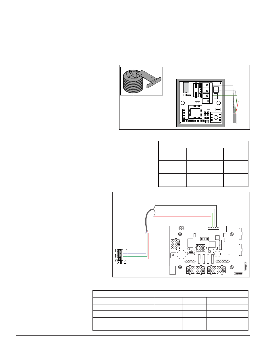
Connection to the Sensor
If it is necessary to reconnect the wires to
the temperature sensor terminal block,
refer to
Figure 6 and the table for the
correct connections.
Note: Make sure the power is off before
making any connections.
Connection from Sensor to the
Display Driver
If the distance from the temperature
sensor to the display is greater than the
provided 25 foot (7.6 m) cable, connect a 4-conductor shielded
cable from the sensor to TB1 on the display driver board.
1. The display’s power must be OFF when attaching the
internal sensor cable to the host driver.
2. Connect the temperature sensor to the terminal
block (TB1) on the host driver. Refer to
and the table for the correct
connections.
1
4
+5V
H
L
G
0
8
GND - Black
CAN L - White
CAN H - Green
+5V - Red
CAN Temperature Sensor Wiring
Figure 6: Temperature Sensor Connection
Wiring to Temperature Sensor
Wire Color Terminal Block
Pin No.
Function
Red
Pin 1
5 V
Green
Pin 2
CAN H
White
Pin 3
CAN L
Black
Pin 4
GND
+5V – Red
CAN H – Green
CAN L – White
GND – Black
1
4
+5V
H
L
G
+5V – Red
CAN H – Green
CAN L – White
Shield GND – Black
Pin 5
Pin 4
Pin 3
Pin 2
Temperature
Sensor
W-1234
CAN Temperature Sensor to MASC Driver
Figure 7: Temperature Sensor to Display Driver Connections
Connections from Temperature Sensor to Host Driver
Temperature Sensor (TB1) Wire Color Function Host Driver (TB1)
Pin 1
Red
5 V
Pin 2
Pin 2
Green
CAN H
Pin 3
Pin 3
White
CAN L
Pin 4
Pin 4
Black
GND
Pin 5