Direct – outdoor connection, 10 electrical installation, Figure 10: direct connection from outdoor location – Daktronics DataTime DF-1012 Time & Temperature Display User Manual
Page 14
10
Electrical Installation
Direct – Outdoor Connection
Reference Drawings:
Riser Diagram, Outdoor Wire Control .....................................................
Drawing A-164988
Time & Temp Power/Signal Hookup .......................................................
Drawing A-938369
Enclosed Driver, 4 Column .....................................................................
Drawing A-938300
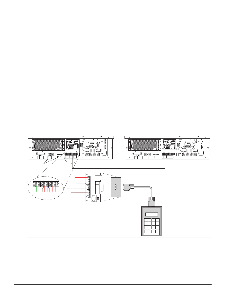
A direct-controlled display uses a current loop connection from the J box at the base of the display to the
driver enclosure in the display. All the power and signal wiring terminates at the driver enclosure. The
DataMaster controller receives its power from the display. The display layout is shown in Drawing A-164988.
Note: The cable from the J box to the display needs to be routed through conduit or the display pole to protect
it from weather and vandalism.
1. Mount the J box at the display.
2. Select the host driver by inserting the Protocol-4 plug into the five-pin protocol jack (J20).
3. Route a six-conductor, 18 AWG, shielded signal cable through conduit from the J box to the driver
enclosure in the host display. Fifty feet (15.2 m) of signal wire is provided.
4. Connect the signal wire from the J box to the driver enclosure as shown in Figure 10 and listed in the
table. Refer to Drawings A-938369 and A-938300 for additional information.
SIGNAL OUT
–
+
J1 24VDC
RADIO J2
SHIELD
–
+
SIGNAL IN
SIGNAL OUT
–
+
J1 24VDC
RADIO J2
SHIELD
–
+
SIGNAL IN
+
+
+
SIGNAL
IN
TB3
SIGNAL
OUT
12V DC
OUT
+
+
+
SIGNAL
IN
TB3
SIGNAL
OUT
12V DC
OUT
GND
GND
TB4
120VAC
LINE
NEUT.
MAIN POWER
TB4
120VAC
LINE
NEUT.
MAIN POWER
0
8 7 6 5
TOP
8 ORG 7 N.C.
6
5 BRN
4
BLK OR SMOOTH
3
2
1
WHT OR GROOVED
0
8 7 6 5
TOP
8 ORG 7 N.C.
6
5 BRN
4
BLK OR SMOOTH
3
2
1
WHT OR GROOVED
Grn Wht
Red
Red
Brn
Blk Blu
Blk
Power/Ground
Connections
Green
White
Brown
Blue
Black
Red
Red
Black
Black and Red =
Signal to Client Display
J-box
DM-100
Controller
1
2
3
4
5
6
7
8
9
Figure 10: Direct Connection from Outdoor Location