Section 4: maintenance and troubleshooting, 1 component location and access, Section 4 – Daktronics DataTime DF-1012 Time & Temperature Display User Manual
Page 19: Maintenance and troubleshooting, Component location and access
Maintenance and Troubleshooting
15
Section 4: Maintenance and Troubleshooting
Important Notes:
• Disconnect power before doing any repair or maintenance work on the display.
• Allow only qualified service personnel access to internal display electronics.
• Disconnect power when not using the display.
4.1 Component Location and Access
Reference Drawings:
Shop Drawings .....................................................................................
Refer to Appendix A
Each display contains an enclosure that includes the following devices:
• Display Driver
• 24V DC Power Supply
• 10V AC Transformer
• Signal Surge Board
• Signal/Power Input Termination Jacks
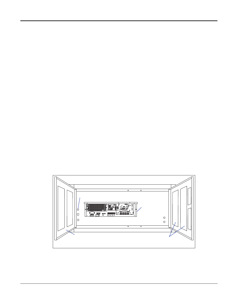
On 10"and 13" displays, all the components are behind one door. For 18" and 24" displays, the hinged doors
swing outward when the two latches on the front display face panel are turned, as shown in
component placement varies slightly with each DataTime
®
model; consult the specific model’s Shop
Drawings.
0
8 7 6 5
TOP
8 ORG 7 N.C.
6
5 BR
N
4
BL
K O
R
SMO
OTH
3
2
1
WH
T O
R
GR
OOVED
TB4
120VAC
LINE
NEUT.
GND
MAIN POWER
+
+
+
SIGNAL
IN
TB3
SIGNAL
OUT
12V DC
OUT
SIGNAL OUT
–
+
J1 24VD
C
RADIO J2
SHIELD
–
+
SIGNAL IN
Temperature Sensor Input
Driver Enclosure
Hinged Door
(Swings Outward)
Digit Circuit Boards
(Mounted to Doors)
Figure 14: Time and Temp Display with Door Panels Open