A.3 external connections – Comtech EF Data RSU-503 User Manual
Page 56
RSU-503 Redundancy Switch Unit
RSU-503L Option
Rev. 8
A–3
A.3 External Connections
Note: The following connections, available on the RSU-503, are not available with the
RSU-503L:
•
TX/RF Input (J3, J7)
•
TX/RF Output (J9)
•
TX/RF Output (J11) (test output only)
C AU TIO N
Failure to properly connect the units will result in loss of communications
between the switch and the RFTs.
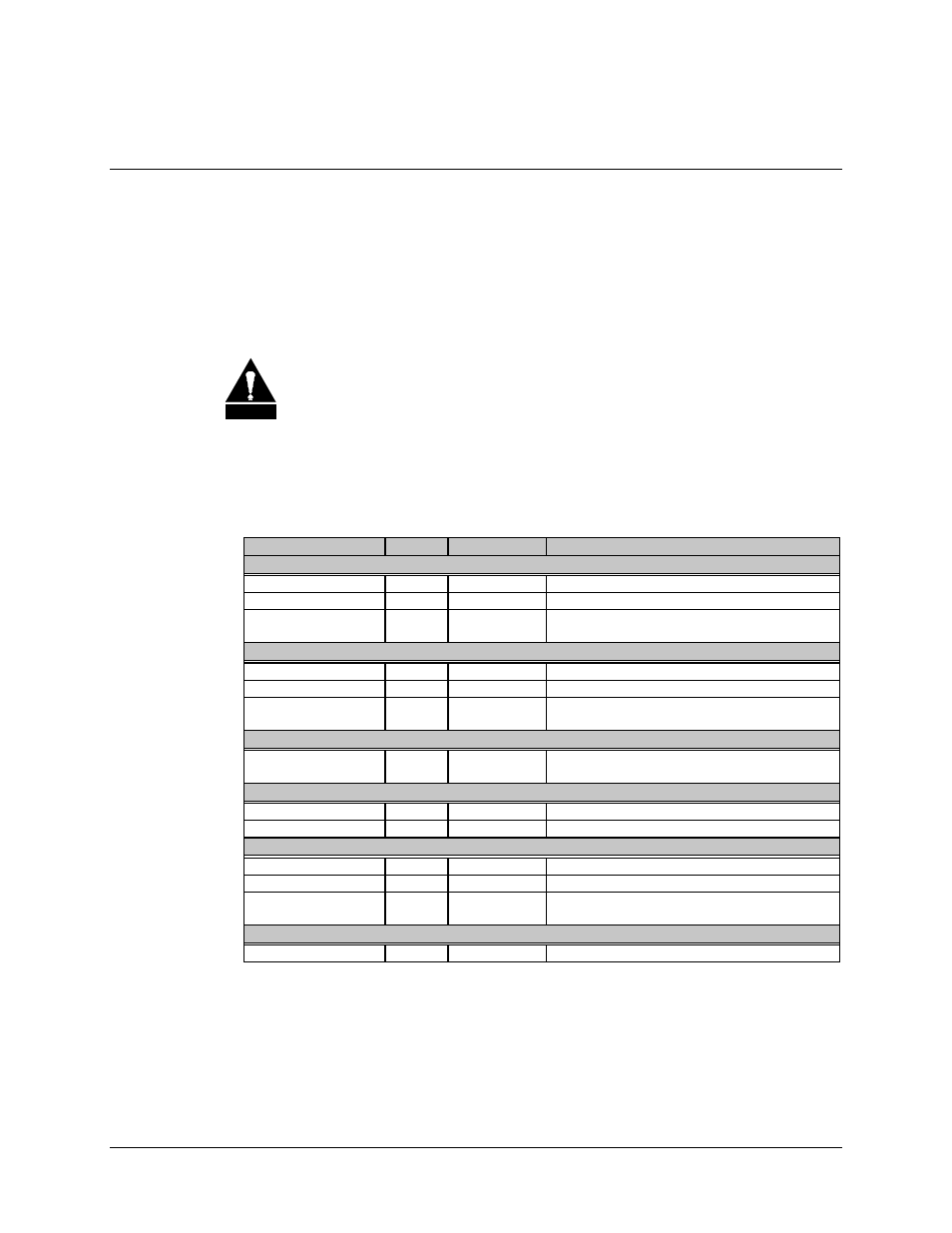
All connections between the switch and other equipment are made through front panel
connections, as shown in Table A-1 (refer to Figure A-3 for connector locations).
Table A-1. RSU-503L External Connections
Name
Desig.
Type
Function
Switch to RFT #A (Primary)
TX/IF OUTPUT
J1
TNC, 50
Ω
IF Uplink to Unit A
RX/IF INPUT
J2
TNC, 50
Ω
IF Downlink from Unit A
MONITOR &
CONTROL
J4
26-pin Circ.
Monitor and control
See Section 2.4.4 for pinouts
(See note
)
Switch to RFT #B (Backup)
TX/IF OUTPUT
J5
TNC, 50
Ω
IF Uplink to Unit B
RX/IF INPUT
J6
TNC, 50
Ω
IF Downlink from Unit B
MONITOR &
CONTROL
J8
26-pin Circ.
Monitor and control
See Section 2.4.4 for pinouts
(See note
)
Switch to Antenna
WAVEGUIDE
SWITCH
J10
19-pin Circ.
Waveguide switch control
See Section 2.4.6.1 for pinouts
Standby Unit Test Ports
TX/IF INPUT
J12
TNC, 50
Ω
IF input test signal
RX/IF OUTPUT
J13
TNC, 50
Ω
IF output test signal
Switch to Modem Terminal Interface
TX/IF INPUT
J14
TNC, 50
Ω
IF Uplink
RX/IF OUTPUT
J15
TNC, 50
Ω
IF Downlink
MONITOR &
CONTROL
J16
26-pin Circ.
Modem Terminal Interface (MTI)
See Section 2.4.12 for pinouts
Ground
GND ERDE
None
#10-32 Stud
Chassis Ground
Note: Refer to Section A.5 for addressing information.