3 m&c input/output signals (j17) – Comtech EF Data RSU-503 User Manual
Page 53
Maintenance
RSU-503 Redundancy Switch Unit
4–8
Rev. 8
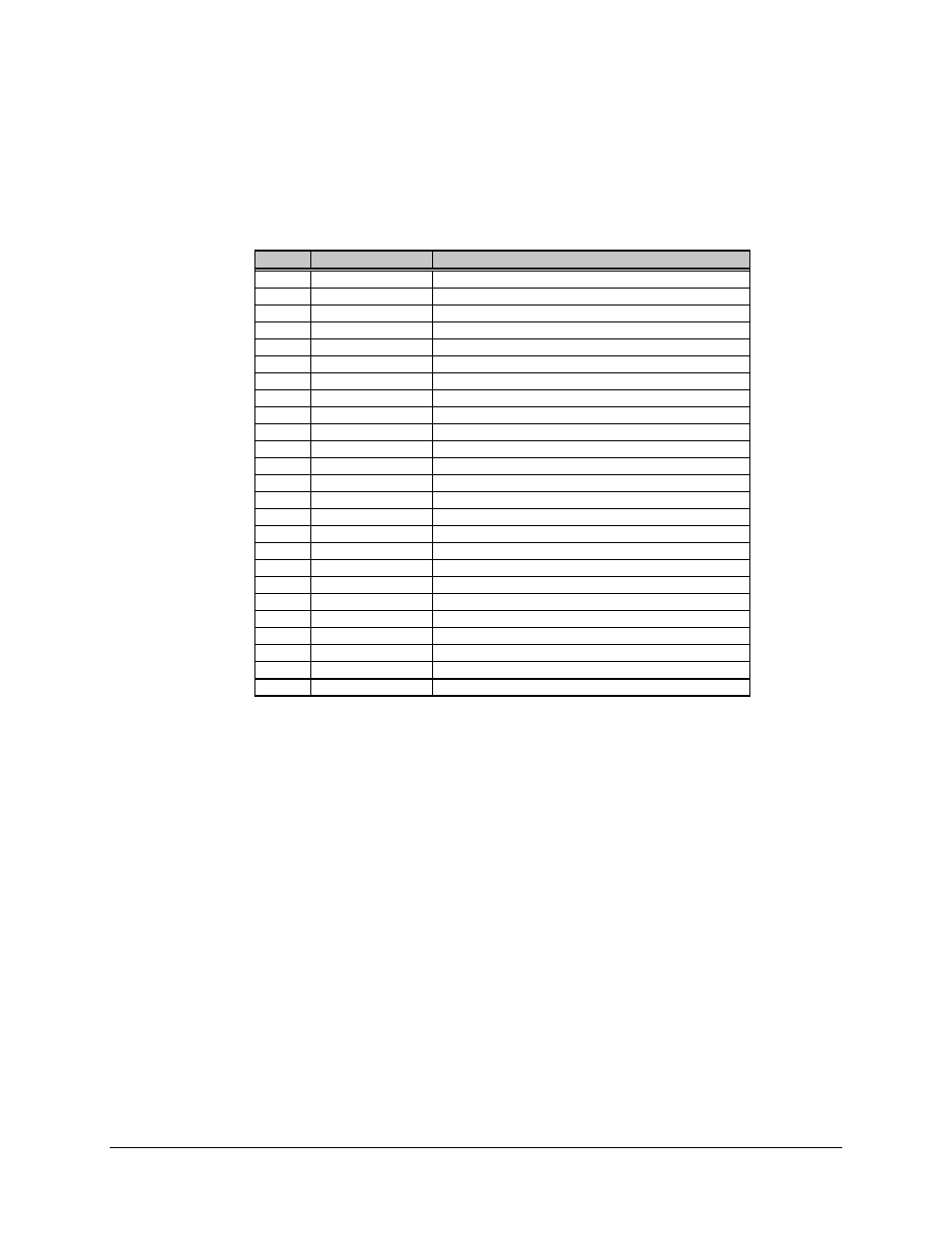
4.5.3 M&C Input/Output Signals (J17)
The M&C I/O connector is a 25-pin male D connector with the following pinouts:
Pin #
Name
Function
13
DC GND A
Tied to signal ground
25
DC GND B
Tied to signal ground
12
UL FLT COM A
Tied to signal ground
24
UL FLT COM B
Tied to signal ground
11
DL FLT COM A
Tied to signal ground
23
DL FLT COM B
Tied to signal ground
10
Spare
22
UL FLT NO A
Input, connected to ground when normal
9
UL FLT NC A
Input, connected to ground when faulted
21
UL FLT NO B
Input, connected to ground when normal
8
UL FLT NC B
Input, connected to ground when faulted
20
Spare
7
DL FLT NO A
Input, connected to ground when normal
19
DL FLT NC A
Input, connected to ground when faulted
6
DL FLT NO B
Input, connected to ground when normal
18
DL FLT NC B
Input, connected to ground when faulted
5
Spare
17
Spare
4
SUM FLT NO
Output, connected to COM when normal
16
SUM FLT COM
Output common
3
SUM FLT NC
Output, connected to COM with any fault
15
Spare
2
XVA
Input, DC power from unit A (approx. 11V)
14
Spare
1
XVB
Input, DC power from unit B (approx. 11V)