2 m&c switch cmd and indicators (j18) – Comtech EF Data RSU-503 User Manual
Page 52
RSU-503 Redundancy Switch Unit
Maintenance
Rev. 8
4–7
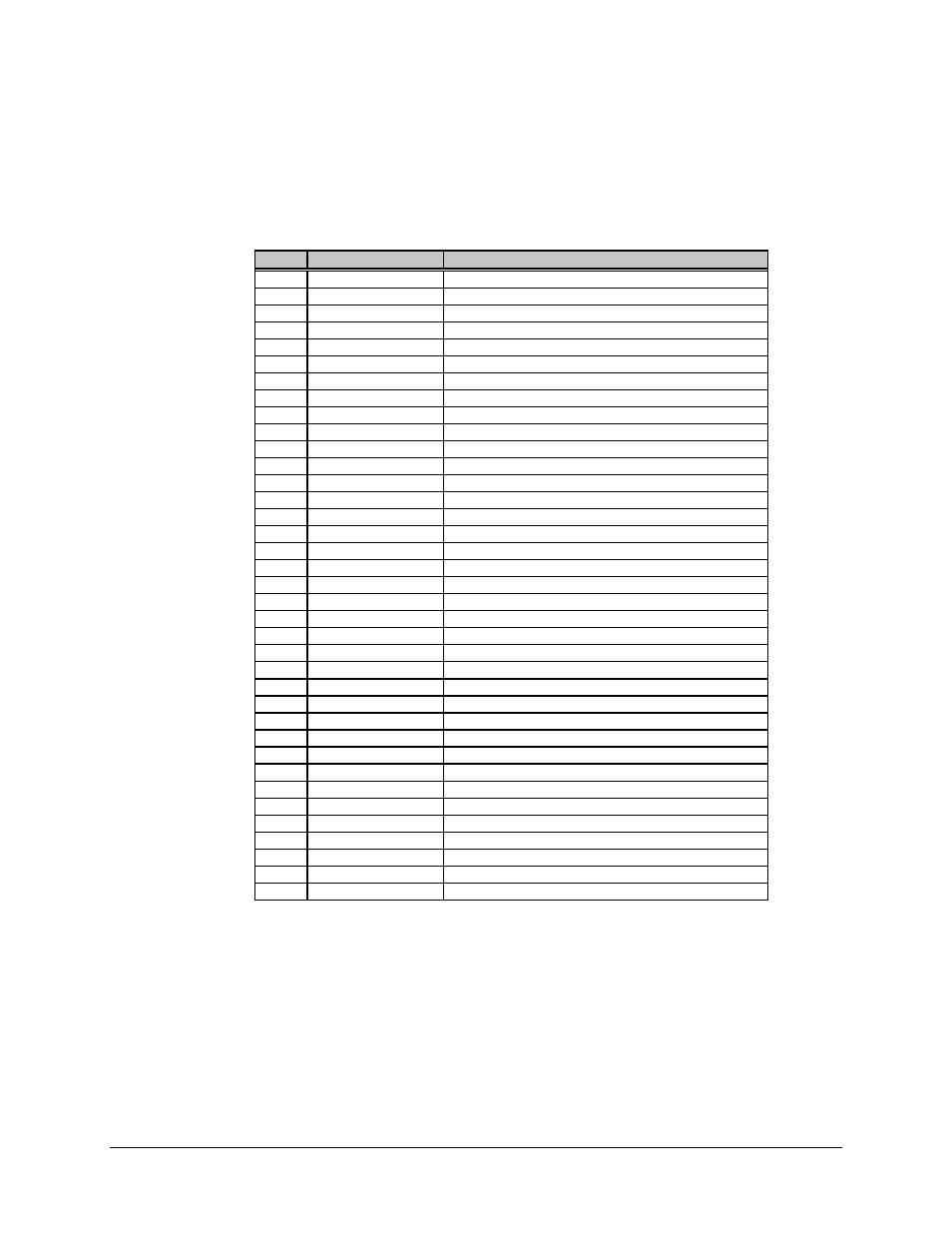
4.5.2 M&C Switch CMD and Indicators (J18)
This connector is a 37-pin female D connector with the following pinouts:
Pin #
Name
Function
1
Terminal Power
Output, 10V power for the KP-10
20
Spare
2
UL IF IND COM
Tied to signal ground
21
DL IF IND COM
Tied to signal ground
3
UL RF IND COM
Tied to signal ground
22
DL RF IND COM
Tied to signal ground
4
Spare
23
UL IF A IND
0V = Indicates uplink IF connected to unit A
5
UL IF B IND
0V = Indicates uplink IF connected to unit B
24
Spare
6
UL RF A IND
0V = Indicates uplink RF connected to unit A
25
UL RF B IND
0V = Indicates uplink RF connected to unit B
7
Spare
26
DL IF A IND
0V = Indicates downlink IF connected to unit A
8
DL IF B IND
0V = Indicates downlink IF connected to unit B
27
Spare
9
DL RF A IND
0V = Indicates downlink RF connected to unit A
28
DL RF B IND
0V = Indicates downlink RF connected to unit B
10
Spare
29
Spare
11
Spare
30
UL IF A CMD
+28V pulse, commands UL IF switch to unit A
12
UL RF A CMD
+28V pulse, commands UL RF switch to unit A
31
Spare
13
UL IF B CMD
+28V pulse, commands UL IF switch to unit B
32
UL RF B CMD
+28V pulse, commands UL RF switch to unit B
14
Spare
33
DL IF A CMD
+28V pulse, commands DL IF switch to A
15
DL RF A CMD
+28V pulse, commands DL RF switch to unit A
34
Spare
16
DL IF B CMD
+28V pulse, commands DL IF switch to unit B
35
DL RF B CMD
+28V pulse, commands DL RF switch to unit B
17
Spare
36
UL IF CMD COM
Tied to signal ground
18
UL RF CMD COM
Tied to signal ground
37
DL IF CMD COM
Tied to signal ground
19
DL RF CMD COM
Tied to signal ground