2 switch indicators – Comtech EF Data RSU-503 User Manual
Page 44
RSU-503 Redundancy Switch Unit
Theory of Operation
Rev. 8
3–3
Although the switch M&C is considered to be the slave unit on the MTI RS-232 bus, it
becomes the master when communicating to each of the two RFTs.
When not servicing MTI requests, the M&C monitors indicators, faults, and voltages.
When applicable, it generates switch-over pulses.
When polled from the MTI, the switch M&C will perform the following functions:
1. Return a response acknowledging receipt of the command.
2. Decode the address in the message, compare it to the stored addresses, and route
it to its intended destination.
3. Return a block of status information when requested.
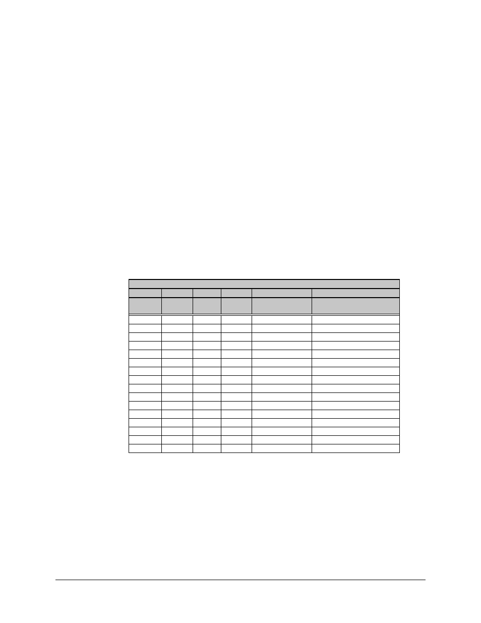
3.4.2 Switch Indicators
Address 9000 reads in the eight indicator bits representing the four uplink and four
downlink indicator positions. The following tables show how the four bits are decoded to
indicate whether the unit A or B is currently online.
Uplink
B0
B1
B2
B3
WR8000, B0
WR8000, B4
IF_A
RF_A
IF_B
RF_B
1 = A ON LINE
0 = B ON LINE
1 = OKAY
0 = AMBIGUITY FAULT
0
0
0
0
1
0
0
0
0
1
1
0
0
0
1
0
1
0
0
0
1
1
1
1 - Valid state, A online
0
1
0
0
0
0
0
1
0
1
0
0
0
1
1
0
0
0
0
1
1
1
0
0
1
0
0
0
1
0
1
0
0
1
1
0
1
0
1
0
1
0
1
0
1
1
1
0
1
1
0
0
0
1 - Valid state, B online
1
1
0
1
0
0
1
1
1
0
0
0
1
1
1
1
0
0