4 m&c (j4, j8) – Comtech EF Data RSU-503 User Manual
Page 34
Installation
RSU-503 Redundancy Switch Unit
18
Rev. 8
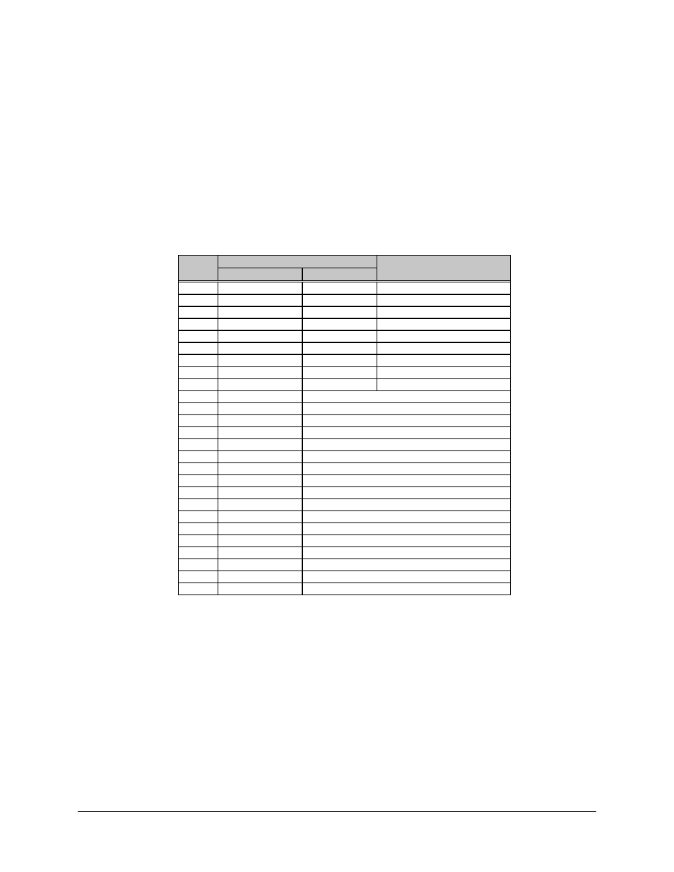
2.4.4 M&C (J4, J8)
The M&C connectors are used to interface with Units A and B, respectively. Included on
these connectors are:
•
Nine RS-232/485 communication pins (A to J)
•
Switch power (L)
•
Fault reporting
The M&C connectors are 26-pin circular female connectors, with the following pinouts:
Pin #
Name
Function
RS-232
RS-485
A
GND
-RX/TX
B
-RX/TX
C
+RX/TX
D
CTS
+RX/TX
Clear to Send
E
TD/TX
Transmit Data
F
RTS
Ready to Send
G
RD/RX
Receive Data
H
DSR
Data Set Ready
J
GND
Ground
K
LNA POWER
10V to LNA
L
EXT POWER
Input Voltage, 11V, 1A max.
M
EXT FLT IN
Fault Input from TWT
N
Reserved
P
N/C
R
GND
Ground
S
Chassis Ground
Ground
T
Reserved
U
UL FLT NC
Fault relay input, closes with Uplink fault
V
UL FLT COM
Fault relay input, COMMON
W
UL FLT NO
Fault relay input, opens with Uplink fault
X
DL FLT NC
Fault relay input, closes with Downlink fault
Y
DL FLT COM
Fault relay input, COMMON
Z
DL FLT NO
Fault relay input, opens with Downlink fault
a
LNA RTN
Ground return from LNA
b
Reserved
c
Reserved
Notes:
1. Clear to Send (CTS) is tied to Ready to Send (RTS) in RS-232 mode.
2. RD/RX and TD/TX are switched in the switch in order to communicate with
the RFTs.