Chp 4 connector pinouts, Data connector - 25 pin ‘d’ type male and female, Chapter 4. connector pinouts – Comtech EF Data CRS-200 User Manual
Page 27
Rev. 1
4–1
4
Chapter 4.
CONNECTOR PINOUTS
4.1
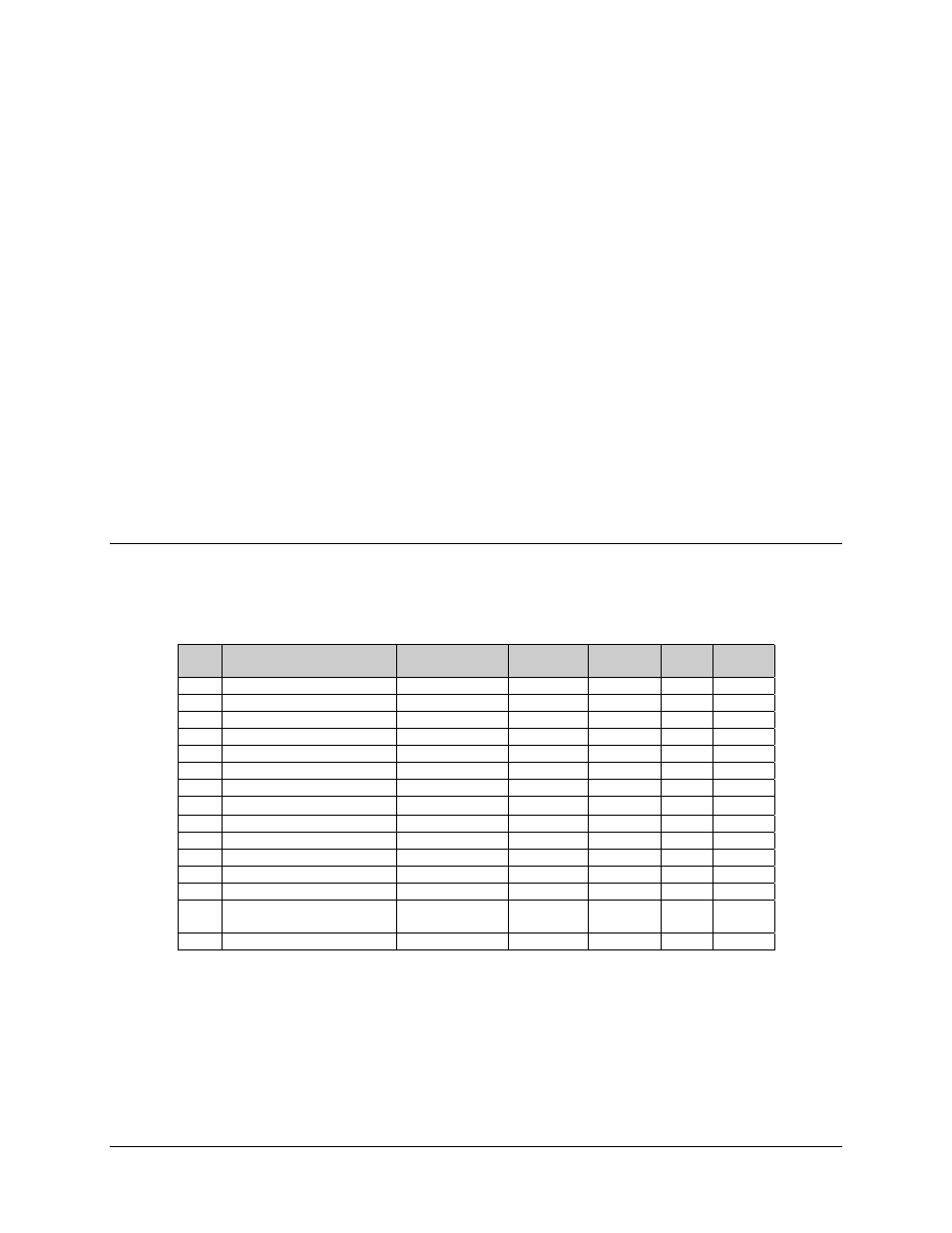
Data Connector - 25 Pin ‘D’ Type Male And Female
Table 4-1 Data Connector
Pin
Generic Signal
description
Direction
EIA-422/
EIA 530
V.35
EIA-
232
Circuit
No
1
Shield
-
Shield
FG
AA
101
2
Transmit Data A
DTE to Modem
SD A
SD A
BA
103
3
Receive Data A
Modem to DTE
RD A
RD A
BB
104
7
Signal Ground
-
SG
SG
AB
102
8
Receiver Ready A
Modem to DTE
RR A
RLSD *
CF
109
9
Receive Clock B
Modem to DTE
RT B
SCR B
-
115
10
Receiver Ready B
Modem to DTE
RR
B
-
109
11
Transmit Clock B
DTE to Modem
TT B
SCTE B
-
113
12
Internal Transmit Clock B
Modem to DTE
ST B
SCT B
-
114
14
Transmit Data B
DTE to Modem
SD B
SD B
-
103
15
Internal Transmit Clock A
Modem to DTE
ST A
SCT A
DB
114
16
Receive Data B
Modem to DTE
RD B
RD B
-
104
17
Receive Clock A
Modem to DTE
RT A
SCR A
DD
115
23
External Carrier Off
(EIA-232 ‘1' or TTL ‘low’)
DTE to Modem
-
-
-
-
24
Transmit Clock A
DTE to Modem
TT A
SCTE A
DA
113
NOTES:
•
Receiver ready is an EIA-232-level control signal on a V.35 interface
•
DO NOT connect signals to pins which are not shown - these pins are reserved for use by the
redundancy system
•
‘B’ signal lines are not used for EIA-232 applications
•
For X.21 operation, use the EIA-422 pins, but ignore Receive Clock if the Modem is DTE, and ignore
Transmit clocks if the Modem is DCE