Alarm interface pin assignment, j1a, j1b, Online status connector pin assignments, j2, 1 alarm interface pin assignment, j1a, j1b – Comtech EF Data CRS-120 User Manual
Page 30: 2 online status connector pin assignments, j2
1:1 Redundancy Switch
Revision 3
Connector Pinouts
MN/CRS120.IOM
3–2
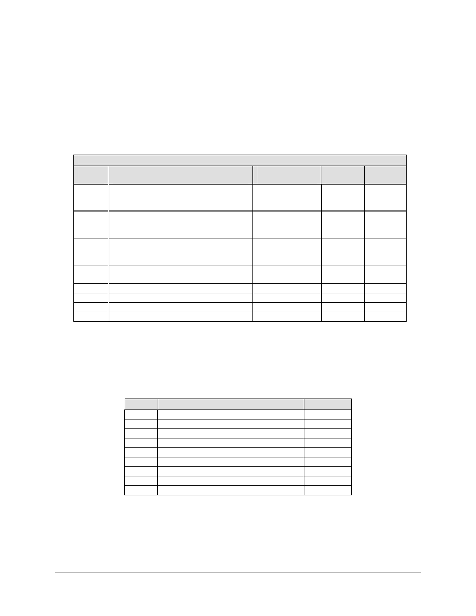
3.1.1 Alarm Interface Pin Assignment, J1A, J1B
The Alarm connector is a 15-Pin D female type, with threaded jack nuts. The pinout depends
upon whether the unit is in the Normal or Redundancy mode.
Alarm A (J1A) or B (J1B) Connector
1:1 Mode (In Modulator)
Pin #
Description
Name
J1A
Direction
J1B
Direction
8
15
7
Program Relay NC
Program Relay NO
Program Relay COM
PR-NC
PR-NO
PR-COM
I/O
I/O
I/O
I/O
I/O
I/O
14
6
13
Rx Fault (De-energized = Open = Fault)
Tx Fault (De-energized = Open = Fault)
Unit Fault (De-energized = Open = Fault)
Rx_-NO
Tx_-NO
Unit_-NO
I/O
I/O
I/O
I/O
I/O
I/O
5
12
4
Mod A/D
+12 VDC Output (160 ma)
AUX0 Out Enable to 1:N
MODA2D
+12Vout
Tx_B_EN
O
I
I
O
I
I
11
3
Rx I Channel (Constellation Monitor)
Rx Q Channel (Constellation Monitor)
Rx-I
Rx-Q
I
I
I
I
10
RS-232 OH Channel Input Tx
Aux_RS232
O
I
2
RS-232 OH Channel Output
Rx Aux_RS232
I
O
9
Ext Carrier Off
EXT-OFF
O
O
1 Ground
GND
Gnd
Gnd
Note: Items shown (NC) are not connected inside the switch.
3.1.2 Online Status Connector Pin Assignments, J2
The Indicator connector is a 9-Pin D female type, with threaded jack nuts.
Pin #
Description
Direction
1 Ground
I/O
2
3
4
B-NO (COM to NO, B is Online)
I/O
5 A/B-COM
I/O
6
A/B-NC (COM to NC, A is Online)
I/O
7
8
9