Figure 1-2. block diagram, Ab d c – Comtech EF Data CRS-120 User Manual
Page 17
1:1 Redundancy Switch
Revision 3
Introduction
MN/CRS120.IOM
1–3
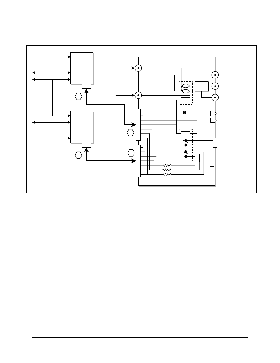
Figure 1-2. Block Diagram
Modulator
A
Modulator
A
Alarm
Modulator
B
Modulator
B
Alarm
Alarm Cable
Tx-B
Tx-A
Data
J4 Tx Online
IF
Coupler
IF
Coupler
J3 Tx Mon -20 dB
RS485
Online Status
Contacts
IF
Switch
CRS-120 or CRS-120L
Ethernet
Ethernet
Data
15
P
in
D-F
J5 Tx Standby
Coil
Coil
15
P
in
D-F
Alarm Cable
+12 VDC
A
B
D
C
Tx A
Tx B
B Online LED
A Online LED
9 Pin D-F
15 Pin D-M
15 Pin D-M
P2
P2
J1
J1
J6A
J6B
J1A
(Top)
J1B
(Bottom)
J2
DIP Switch
Standby
Tx IF Out
B
A
See also other documents in the category Comtech EF Data Equipment:
- CDD-880 (124 pages)
- CDM-800 (130 pages)
- ODMR-840 (184 pages)
- CDM-750 (302 pages)
- CDM-840 (244 pages)
- SLM-5650A (420 pages)
- CTOG-250 (236 pages)
- CDM-700 (256 pages)
- CDM-760 (416 pages)
- CDM-710G (246 pages)
- CDM-600/600L (278 pages)
- CDMR-570L (512 pages)
- CDM-625 (684 pages)
- CDM-625A (756 pages)
- CDD-564A (240 pages)
- CDD-564L (254 pages)
- CLO-10 (134 pages)
- MCED-100 (96 pages)
- CDMR-570AL (618 pages)
- CDM-600 LDPC (2 pages)
- BUC Power Supply Ground Cable (2 pages)
- MPP70 Hardware Kit for CDM-570L (4 pages)
- MPP50 Hardware Kit for CDM-570L (4 pages)
- CDM-625 DC-AC Conversion (4 pages)
- CDM-625 DC-AC Conversion with IP Packet Processor (4 pages)
- DMDVR20 LBST Rev 1.1 (117 pages)
- DMD2050E (212 pages)
- DMD-2050 (342 pages)
- DMD1050 (188 pages)
- OM20 (220 pages)
- QAM256 (87 pages)
- DD240XR Rev Е (121 pages)
- MM200 ASI Field (5 pages)
- DM240-DVB (196 pages)
- MM200 (192 pages)
- CRS-150 (78 pages)
- CRS-280L (64 pages)
- CRS-170A (172 pages)
- CRS-180 (136 pages)
- SMS-301 (124 pages)
- CiM-25/8000 (186 pages)
- CiM-25 (26 pages)
- CRS-500 (218 pages)
- CRS-311 (196 pages)
- CIC-20 LVDS to HSSI (26 pages)