Connector pinouts, External modem connections, Chapter 3. connector pinouts – Comtech EF Data CRS-120 User Manual
Page 29: 1 external modem connections
3–1
Chapter 3. CONNECTOR PINOUTS
3.1 External
Modem
Connections
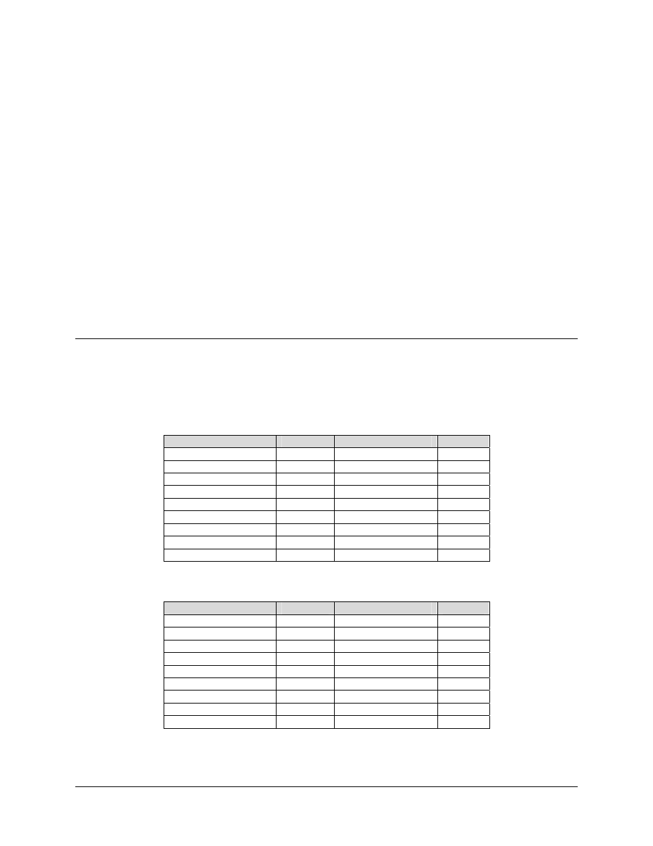
The external connectors provide all necessary connections between the 1:1 switch and other
equipment. Refer to Figures 1-3 and 1-4 for appropriate connector locations.
Table 3-1. CRS-120 Connectors and Pin Assignments
Name
Reference
Connector Type
Function
Alarm Interface, Top
J1A
15-Pin D Sub/Female
Alarm Interface, Bottom J1B
15-Pin D Sub/Female
Online Status
J2
9-Pin D Sub/Female
TX-IF MON
J3
BNC Female
TX-IF Online
J4
BNC Female
TX-IF Standby
J5
BNC Female
TX IF A
J6A
BNC Female
TX IF B
J6B
BNC Female
Ground GND
10-32
Stud
Table 3-2. CRS-120L Connectors and Pin Assignments
Name
Reference
Connector Type
Function
Alarm Interface, Top
J1A
15-Pin D Sub/Female
Alarm Interface, Bottom J1B
15-Pin D Sub/Female
Online Status
J2
9-Pin D Sub/Female
-20 dB MON
J3
SMA Female
Online
J4 SMA
Female
Standby
J5 SMA
Female
TX IF A
J6A
SMA Female
TX IF B
J6B
SMA Female
Ground GND
10-32
Stud