Crs-120 optional mounting panel, 1 crs-120 optional mounting panel – Comtech EF Data CRS-120 User Manual
Page 24
1:1 Redundancy Switch
Revision 3
Installation
MN/CRS120.IOM
2–2
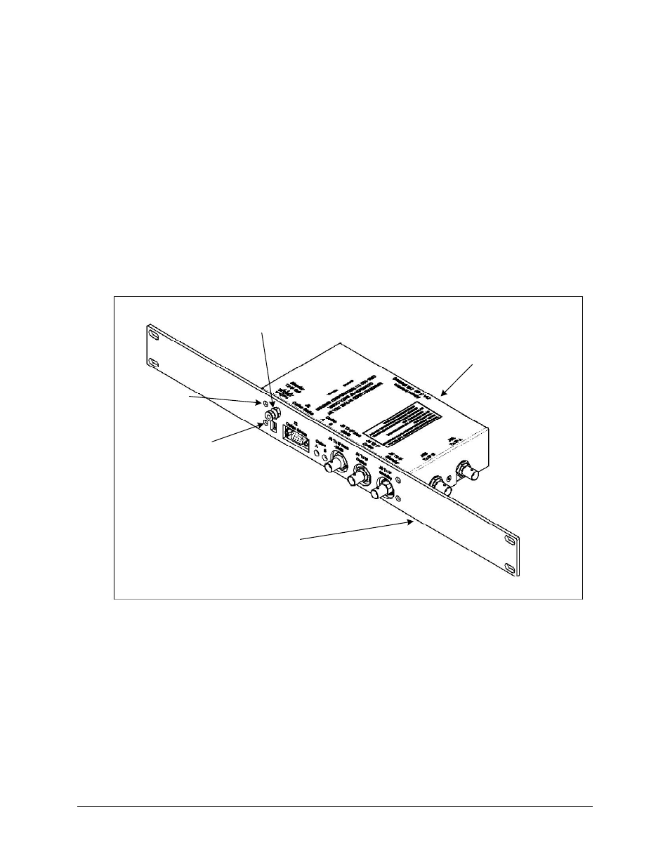
2.2.1 CRS-120 Optional Mounting Panel
An optional mounting panel (KT/11084-2) is available to attach the 1:1 redundancy switch to the
standard 19-inch cabinet. Install Mounting Panel as follows:
1. Remove two bottom switch screws (Figure 2-1)and set a side.
2. Remove two upper switch screws and discard.
3. Remove grounding nuts and washers from grounding lug and set aside.
4. Position mounting panel onto switch.
5. Reinstall gounding nuts and washers previously removed.
6. Reinstall two bottom switch screws previously removed.
7. Install two kit screws (component of KT/11084-2) and secure.
CRS-120 Switch
Optional: Mounting Panel
Grounding Lug Nuts and
Washers
Switch Screw
(Typical 2 Places)
Kit Screw
(Typical 2 Places)
Figure 2-1. CRS-120 Optional Mounting Panel
- CDD-880 (124 pages)
- CDM-800 (130 pages)
- ODMR-840 (184 pages)
- CDM-750 (302 pages)
- CDM-840 (244 pages)
- SLM-5650A (420 pages)
- CTOG-250 (236 pages)
- CDM-700 (256 pages)
- CDM-760 (416 pages)
- CDM-710G (246 pages)
- CDM-600/600L (278 pages)
- CDMR-570L (512 pages)
- CDM-625 (684 pages)
- CDM-625A (756 pages)
- CDD-564A (240 pages)
- CDD-564L (254 pages)
- CLO-10 (134 pages)
- MCED-100 (96 pages)
- CDMR-570AL (618 pages)
- CDM-600 LDPC (2 pages)
- BUC Power Supply Ground Cable (2 pages)
- MPP70 Hardware Kit for CDM-570L (4 pages)
- MPP50 Hardware Kit for CDM-570L (4 pages)
- CDM-625 DC-AC Conversion (4 pages)
- CDM-625 DC-AC Conversion with IP Packet Processor (4 pages)
- DMDVR20 LBST Rev 1.1 (117 pages)
- DMD2050E (212 pages)
- DMD-2050 (342 pages)
- DMD1050 (188 pages)
- OM20 (220 pages)
- QAM256 (87 pages)
- DD240XR Rev Е (121 pages)
- MM200 ASI Field (5 pages)
- DM240-DVB (196 pages)
- MM200 (192 pages)
- CRS-150 (78 pages)
- CRS-280L (64 pages)
- CRS-170A (172 pages)
- CRS-180 (136 pages)
- SMS-301 (124 pages)
- CiM-25/8000 (186 pages)
- CiM-25 (26 pages)
- CRS-500 (218 pages)
- CRS-311 (196 pages)
- CIC-20 LVDS to HSSI (26 pages)