Comtech EF Data CRS-120 User Manual
Page 28
1:1 Redundancy Switch
Revision 3
Installation
MN/CRS120.IOM
2–6
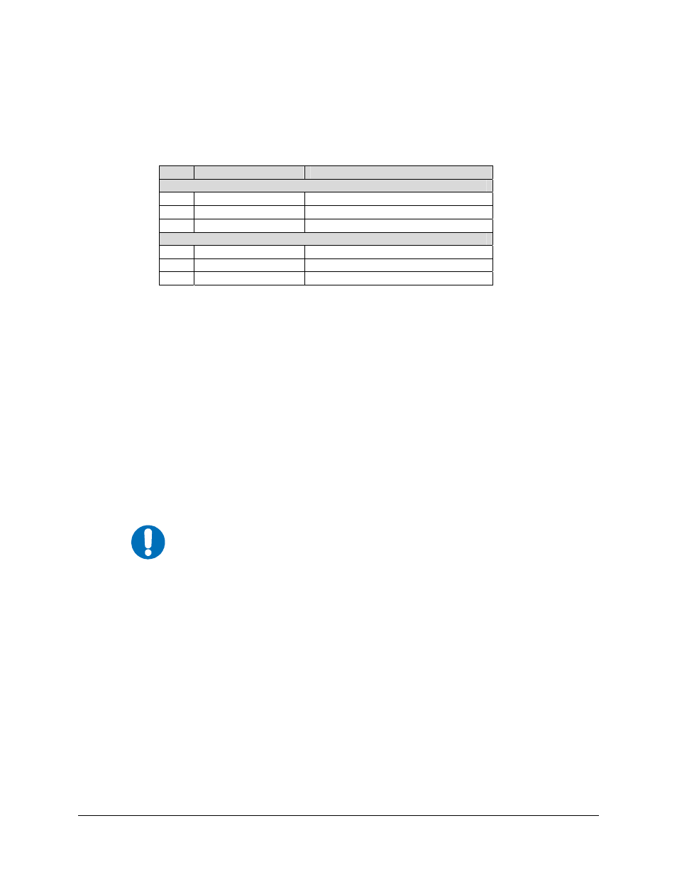
The following cable assemblies are available with the 1:1 redundancy switch as shown in the
preceding figure:
Qty
Cable, P/N
Remarks
CRS-120
2
CA/WR11002-2
Cable Assy, Alarms Interface
2 CA/BNC75OHM
CEFD, 75
Ω IF Cable
REF KT/11084-3
CRS-120 Switch Kit (including cabling)
CRS-120L
2
CA/WR11002-2
Cable Assy, Alarms Interface
2 CA/RF-5785-24
CEFD,
L-Band
Cable
REF KT/11362-3
CRS-120L Switch Kit (including cabling)
For CRS-120 Switch: The 1:1 redundancy switch is designed to work with 75
Ω systems, and
Users should ensure that they order the correct IF cable sets.
For CRS-120L Switch: The 1:1 redundancy switch is designed to work with 50
Ω systems, and
users should ensure that they order the correct L-Band cables.
The modulator connected to the J1A (top) connector of the 1:1 redundancy switch is recognized
as the A unit and the one connected to J1B is the B unit. When a modulator is plugged in and
detected the main menu of the front panel display automatically indicates whether the modem is
A or B.
It is essential to ensure that the IF connections, are made correctly, ie the TX IF from Unit ‘A’
connects to the TX IF port ‘A’ on the 1:1 redundancy switch, and Unit ‘B’ to ‘B’. Failure to
observe this requirement will result in the system malfunctioning.
IMPORTANT
When connecting the Alarms Interface cable between the 1:1 redundancy
switch and the modulators, please ensure that screw locks on the ‘D’ type
connectors are securely fastened. This will prevent the accidental un-
mating of the cable, particularly when a Standby unit is being removed or
replaced.