3 if in connector (j3), 4 if out connector (j4), 5 rx mon connector (j5) – Comtech EF Data KST-2000L User Manual
Page 36
Satellite Terminal System
Revision 2
Connector Pinous
MN/KST2000L.IOM
5
9
4
8
3
2
1
6
7
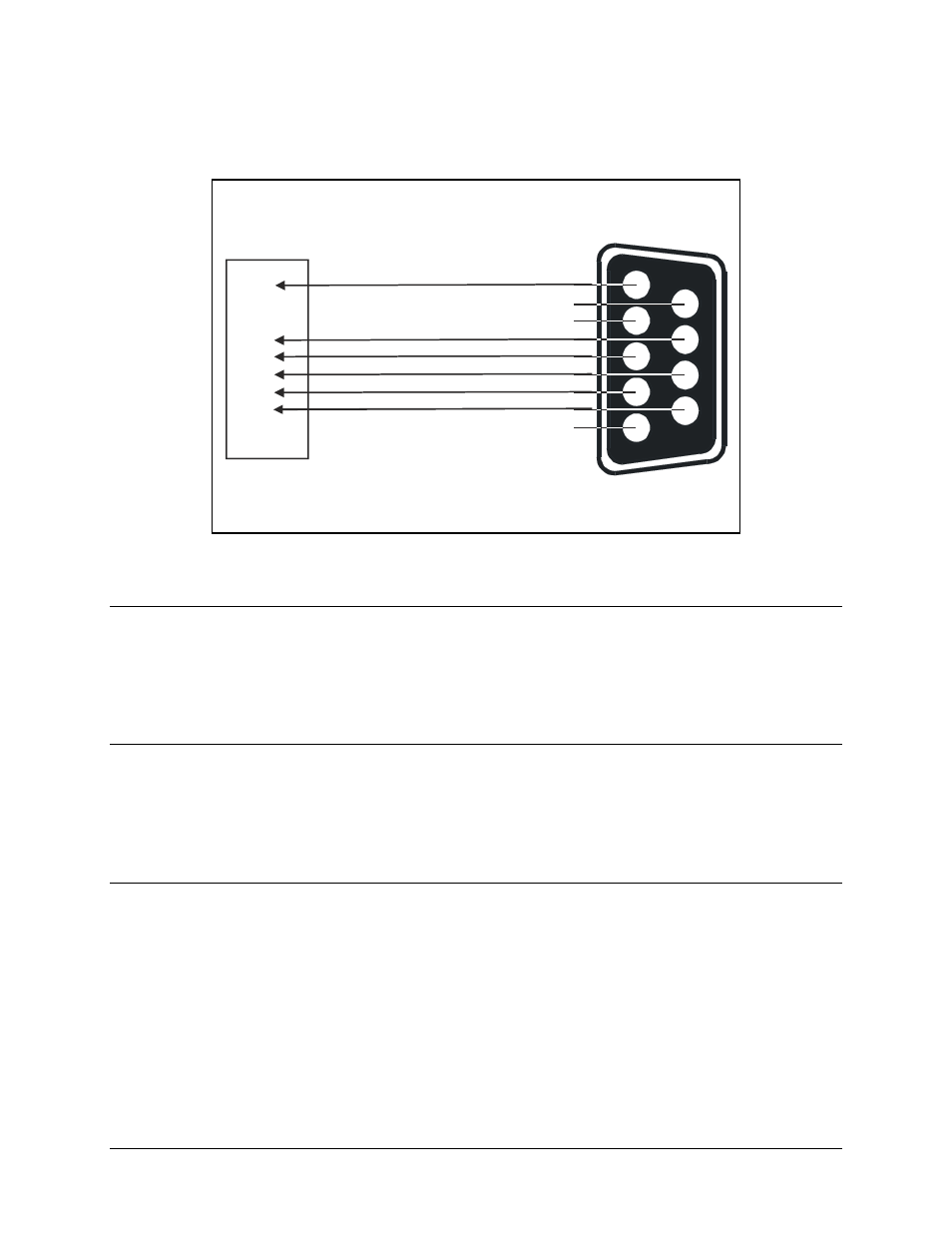
GND
CTS
RD/R
RTS
TD/T
DSR
EIA-232 ADAPTER CABLE
J
P
E
F
G
H
Comtech EF Data: CN/STPG26M01
PT06E16-26P(SR)
26 PIN
MALE
P1
Figure 3-2. Serial (EIA-232) Adapter Cable Wiring Diagram
3.2.1.3
IF IN Connector (J3)
The IF IN connector (J3) is a Type N, female connector used to connect the IF at 70 MHz
(140 MHz optional) at –25 to – 45 dBm from the modem to the converter unit. Either
50
Ω or 75Ω cables may be used to connect to J3.
3.2.1.4
IF OUT Connector (J4)
The IF OUT connector (J4) is a Type N, female connector used to connect the IF at
70 MHz (140 MHz optional) from the converter unit to the modem. Either 50
Ω or 75Ω
cables may be used to connect to J4.
3.2.1.5
RX MON Connector (J5)
The RX Mon (J5) connector provides the received (downlink) signal at L-Band (950 to
1700 MHz) for monitoring. This signal has a gain of 20 dB relative to the carrier. J5 is a
Type N, female connector. Nominal output impedance is 50
Ω.
3–6