1 prime power connector (j1) – Comtech EF Data KST-2000L User Manual
Page 34
Satellite Terminal System
Revision 2
Connector Pinous
MN/KST2000L.IOM
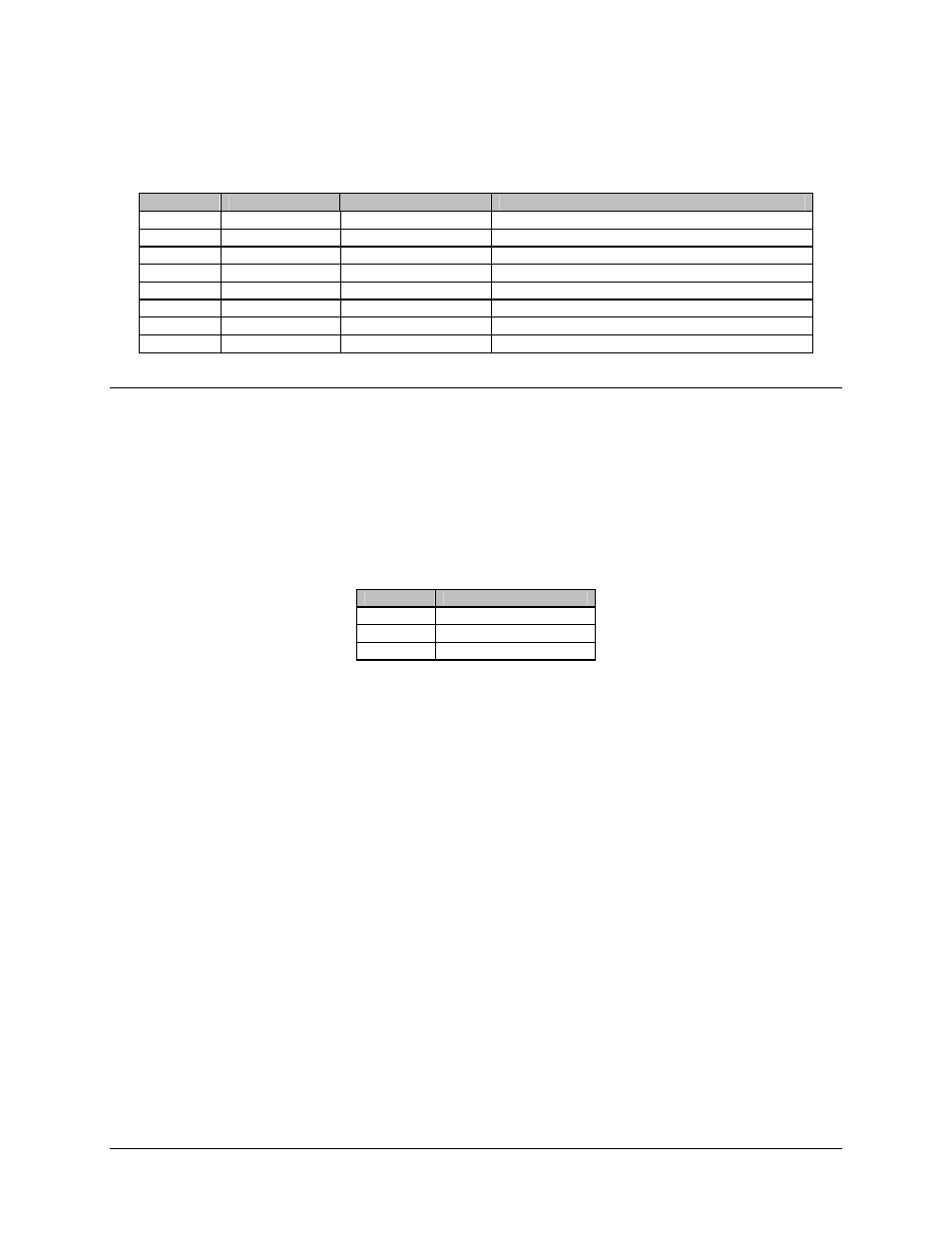
Table 3-3. Converter Unit External Connections
Ref. Des.
Name
Connector Type
Function
J1
PRIME POWER
3 pin circular Male
Prime AC Power Input
J2
REMOTE
26 pin circular, Female
Remote M&C Interface
J3
IF IN
Type N, Female
TX IF Input 70 MHz (Optional: 140 MHz)
J4
IF OUT
Type N, Female
RX IF Output 70 MHz (Optional: 140 MHz)
J5
RX MON
Type N, Female
Ku-Band Receive Monitor (950 to 700MHz)
J6
RF OUT
Type N, Female
14.00 to 14.50 GHz TX out to HPA
J7
RF IN
Type N, Female
950 to 1700 MHz from LNB
J8
HPA
10 pin circular, Stet
HPA M&C Interface
3.2.1.1
Prime Power Connector (J1)
Prime power is supplied to the converter unit through a 3–pin circular male connector
(J1). Prime power input requirements are 85 to 264 VAC, 47 to 63 Hz, 100 watts. The J1
connections are listed in Table 3-4 for pin assignments.
Note: Pin C is adjacent to the connector notch.
Table 3-4. Prime Power Input (J1) Pin Assignments
Pin
Function
A Line
B Neutral
C Ground
3–4