3 control and data connections – crs-300 to modem, Ee table 4-1 – Comtech EF Data CRS-300 User Manual
Page 95
CRS-300 1:10 Redundancy Switch
MN/CRS300.IOM
Cables and Connections
Revision 19
4–21
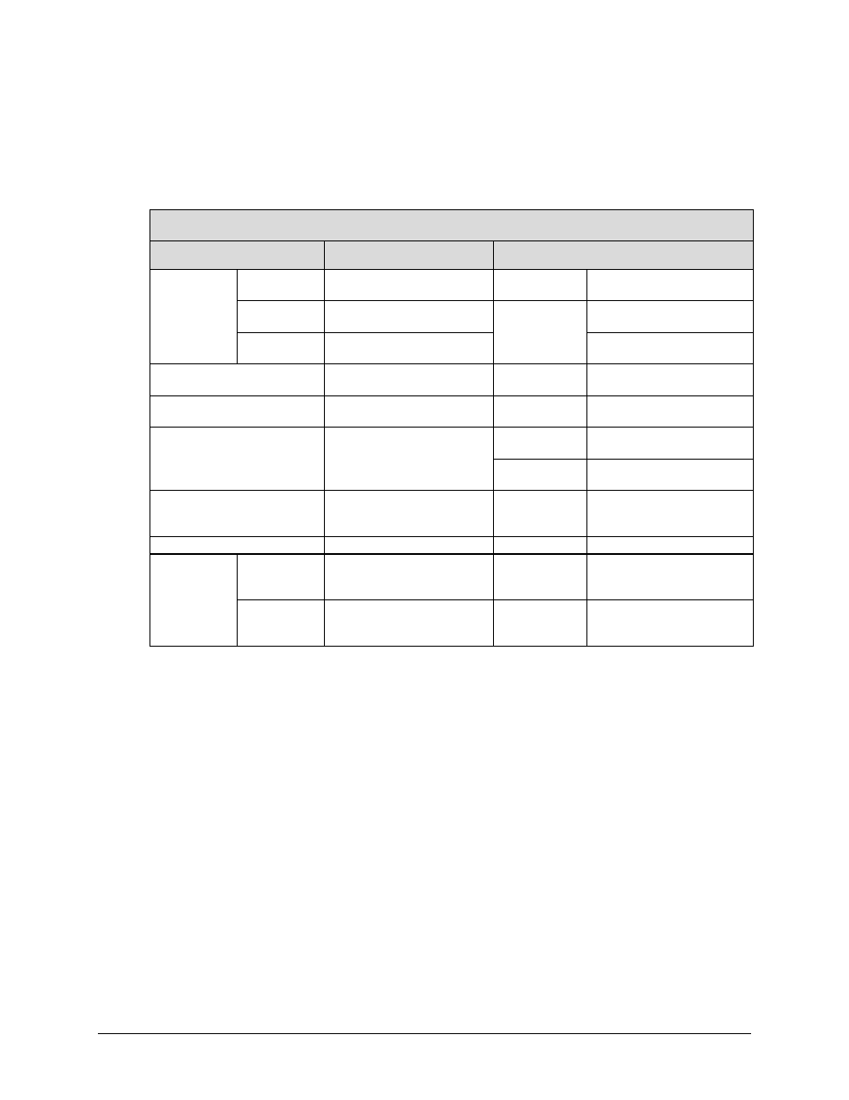
4.4.3 Control and Data Connections – CRS-300 to Modem
Table 4-1 shows the TMI and applicable data and control cables that you will need for each of
the various data types.
Table 4-1. CDM-625/A Cable Usage (RMI/TMI)
CDM-625/A Cable Usage
(see Appendix B. CABLE DRAWINGS for cable details)
Driving Traffic Data Type
CRS-310 RMI / Cable(s)
TMI / Cable(s)
G.703
(Sect. 4.4.3.2)
Bal/Unbal
Control: CA/WR0066
Data: CA-0000072
CRS-330/340
Control: CA/WR0066
Data: CA-0000072
Balanced
Control: CA/WR0066
Data: CA-0000072
CRS-325
Control: CA/WR0066
Data: CA-0000072
Unbalanced
Control: CA/WR0066
Data: PL/0813-8 (2X)
Control: CA-0000069
Data: PL/0813-8 (2X)
G.703 – Quad E1
(Sect. 4.4.3.3)
Control: CA/WR0066
Data: CA-0000073
CRS-365D
Control: CA-0000069
Data: CA-0000136 (2X)
ASI (Sect. 4.4.3.4)
Control: CA/WR0066
Data: PL/0813-8 (2X)
CRS-325
Control: CA-0000069
Data: PL/0813-8 (2X)
EIA-422 (Sect. 4.4.3.5)
Control/Data: CA/WR0066
CRS-316
Control: CA-0000069
Data: CA/WR0066
CRS-340
Control: CA/WR0066
Data:
HSSI (Sect. 4.4.3.6)
Control/Data: CA/WR0066
CRS-336
Control: CA-0000069
Data: CA/WR9189-6 with CIC-60
Adapter Module
LVDS (Sect. 4.4.3.7)
Control/Data: CA/WR0066
CRS-340
Control/Data: CA/WR0066
Ethernet
(Sect. 4.4.3.8)
Wired-thru
(No Sub-Mux)
(Sect. 4.4.3.8.1)
Control: CA/WR0066
Data: CA-0000121
CRS-316 or
CRS-336
Control: CA-0000069
Data: PP/CAT5FF7FTGY
Wired-around
(Sub-Mux)
(Sect. 4.4.3.8.2)
Control: CA/WR0066
Data (by User): CAT5 to
10/100/1000 Switch
N/A
N/A
4.4.3.1 Control Cabling Requirement (Regardless of Driving Traffic Data
Type)
For RMI connections: The Control/Data Cable CA/WR0066 (DB-25F to DB-25M, 6’) provides the
serial communication path between the Redundant CDM-625/A and the Switch (via the CRS-310
RMI) for all driving traffic data types. You must always use this cable.
For all driving traffic data types, see Figure 4-9 through Figure 4-11 and do these steps to
connect and secure the CA/WR0066 cable between the Redundant CDM-625/A and the Switch
CRS-310 RMI:
•
DB-25F connector labeled “Data Interface” on Redundant CDM-625/A, to
•
DB-25M connector labeled “P1” on the Switch CRS-310 RMI.
For TMI connections: Depending on the driving data traffic type, in addition to its use as a
control cable between the Redundant CDM-625/A and the CRS-310 RMI, you may use the