Venting installation instructions, Continued – Desa (V) CD36R(N User Manual
Page 10
10
www.desatech.com
116035-01B
VENTING INSTALLATION INSTRUCTIONS
Installation Planning (Cont.)
VENTING INSTALLATION
INSTRUCTIONS
Continued
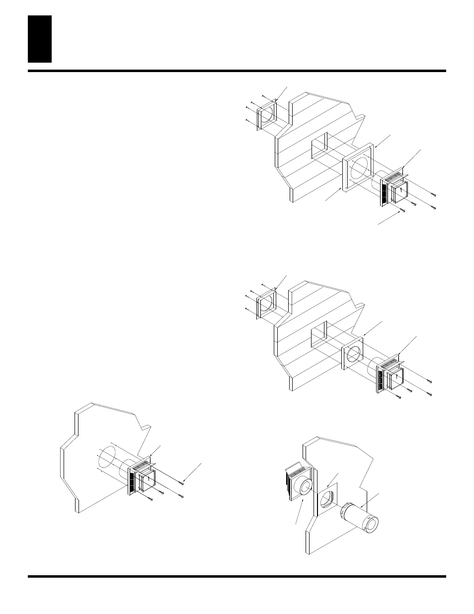
6. Noncombustible Exterior Wall: Position the horizontal vent
cap in the center of the 8 ½” round hole and attach to the exte-
rior wall with four wood screws provided. Before attaching
the vent cap to exterior wall, run a bead of non-hardening mastic
(pliable sealant) around the outside edges to make a seal be-
tween it and the outside wall. Note: The four wood screws
provided should be replaced with appropriate fasteners for
stucco, brick, concrete, or other types of sidings. (See Figure 13).
Combustible Exterior Wall:
For vinyl siding, stucco or wood
exteriors, a siding standoff may be installed between the vent
cap and exterior wall. The siding standoff prevents excessive
heat from damaging the siding materials. Siding material must
be cut to accommodate standoff. Bolt the vent cap to the stand-
off. Apply non-hardening mastic around outside edge of stand-
off. Position the standoff/cap assembly in the center of the
10 ¾ square hole and attach to exterior wall with wood
screws provided (see Figure 14). The siding standoff must sit
flush against the exterior fascia material.
7. Combustible Exterior Wall Only: Fit the outer and inner wall
firestop into the wall before connecting horizontal run to vent
cap (see Figure 15).
8. Carefully move fireplace, with vent assembly attached, toward
wall and insert vent pipe into horizontal termination. The pipe
overlap should be a minimum of 1 ¼”.
9. Combustible Exterior Wall Only: Slide wall firestop against
interior wall surface and attach with screws provided (see Figure
16). See Figure 17 for horizontal termination details.
10. Place fireplace into position and shim with noncombustible ma-
terial, if needed. Nail or screw flanges to framing to secure
unit in place. IMPORTANT: Make sure fireplace is level before
securing. If fireplace is not level, it will not work properly.
VENT
CAP
INNER WALL
FIRESTOP
VINYL
SIDING
STANDOFF
HO
T
APPLY
MASTIC
TO ALL SIDES
SCREWS
Figure 14 - Installing Siding Standoff
INNER WALL
FIRESTOP
VENT
CAP
OUTER WALL
FIRESTOP
HO
T
Figure 15 - Installing Outer Wall Firestop
INNER WALL
FIRESTOP
PIPE SECTION
VENT
CAP
Figure 16 - Installing Inner Wall Firestop
SCREWS
VENT
CAP
HO
T
Figure 13 - Installing Horizontal Vent Cap (Noncombustible)