2 tracing, 3 pt100 tracing sensor, 4 communication – Bronkhorst Vapor Delivery Module User Manual
Page 10: 1 rs232 / propar, 2 flow-bus, Tracing, Pt100 tracing sensor, Communication, Rs232 / propar, Flow-bus
Bronkhorst®
Vapor Delivery Module
9.17.079
10
For mains connection, use appropriate cabling with IEC 60320-1/C19 connector:
• Power cable with Euro Plug (EU) – Schurter #6051.2043 (art.nr.1.15.242)
• Power cable with Switzerland Plug (CH) (art.nr.1.15.243)
• Power cable with North America Plug (USA) – Schurter #6051.2041 (art.nr.1.15.244)
• Power cable with United Kingdom Plug (UK) – Schurter #6051.2048 (art.nr.1.15.245)
3.6.2
Tracing
Optionally, the Vapor Delivery Module can be provided with a trace temperature control. In this case, the VDM-Series is provide
with a tracing output IEC 60320-2-2 / C13 female connector. This connector is intended for connecting tracing tape, which is not
supplied. The voltage at this tracing output is equal to the supply voltage of the Vapor Delivery Module.
For tracing connection, use appropriate cabling with IEC 60320-2-2/C14 plug (art.nr. 1.09.594). Make sure cabling is double
isolated.
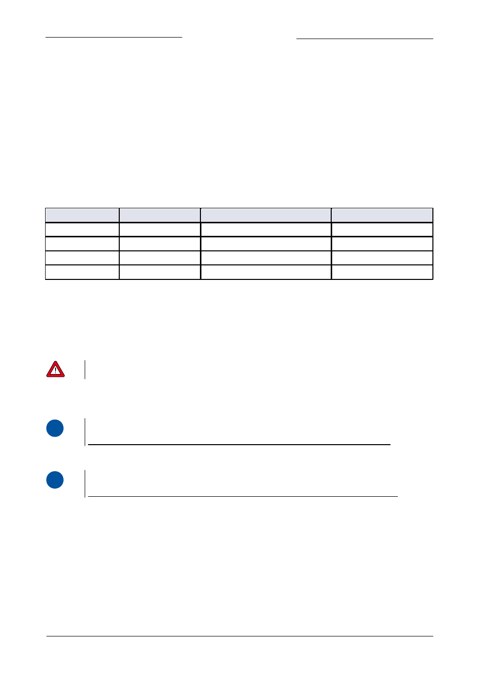
The table below shows the maximum tracing power and the fuse amperage for the various models.
Model
Power supply (Vac)
Maximum tracing power
Fuse tracing heater
SW-10n-n-51-a-nn-a
110 … 120
300 VA 50-60 Hz
T2,5A
SW-20n-n-51-a-nn-a
110 … 120
300 VA 50-60 Hz
T2,5A
SW-10n-n-31-a-nn-a
220 … 240
300 VA 50-60 Hz
T1,25A
SW-20n-n-31-a-nn-a
220 … 240
300 VA 50-60 Hz
T1,25A
3.6.3
Pt100 tracing sensor
Optionally, the Vapor Delivery Module can be provided with a trace temperature control. In this case, the VDM-Series is provide
with a Pt100 inlet 4-pin M12 A-coded male connector. This connector is intended for connecting a two, three or four-wire Pt100.
Measurement current through the sensor is 0,5 mA.
For Pt100 connection, use appropriate cabling with M12 4-pin female connector (art.nr. 1.09.593).
Warning! Be sure that the temperature sensor is properly mounted with the tracing wire,
otherwise no temperature control is possible and hazardous situations may occur.
3.6.4
Communication
3.6.4.1 RS232 / Propar
i
www
For further instructions about the RS232 interface see manual 9.17.027 Manual 'RS232 interface with FLOW-BUS
protocol for digital instruments'. This manual is available at the download section of our website:
3.6.4.2 FLOW-BUS
i
www
For further instructions about the FLOW-BUS interface see manual 9.17.024 Manual 'FLOW-BUS interface for digital
instruments'. This manual is available at the download section of our website: