5 valve principles, Ck φ – Bronkhorst Mass Flow User Manual
Page 9
BRONKHORST HIGH-TECH B.V.
flow control
valve
flow control
valve
pressure
compensating
valve
P2
P1
temperature difference between the upstream and the downstream leg of the measuring tube by means
of a thermopile. The simplified transfer function can be described according to the following equation:
V
signal
=
m
p
c
K
Φ
⋅
⋅
V
signal
= output signal
K
= constant factor
c
p
= specific heat
Φ
m
= mass flow
1.4.3 Pressure sensor
The EL-PRESS pressure sensor is formed by a piezoresistive bridge on the surface of a silicon crystal.
The sensor is mounted in a stainless steel construction and separated from the fluid by a thin metal
membrane. The chamber around the sensor is filled with oil to couple the pressure from the fluid to the
sensor.
1.5 Valve principles
Control valves are not designed to provide positive shut-off, although some models have excellent
capabilities for this purpose.
It is recommended to install a separate shut-off valve in the line if so required. Also pressure surges, as may
occur during system pressurisation must be avoided. The following models can be distinguished:
1.5.1 Solenoid valve
This is considered to be the standard (direct operated) control valve. In
general it is a normally closed solenoid valve. The plunger is lifted by
the force of the magnetic field of the coil. The orifice under the plunger
is removable for optimising the orifice diameter. Also a normally opened
solenoid valve is available.
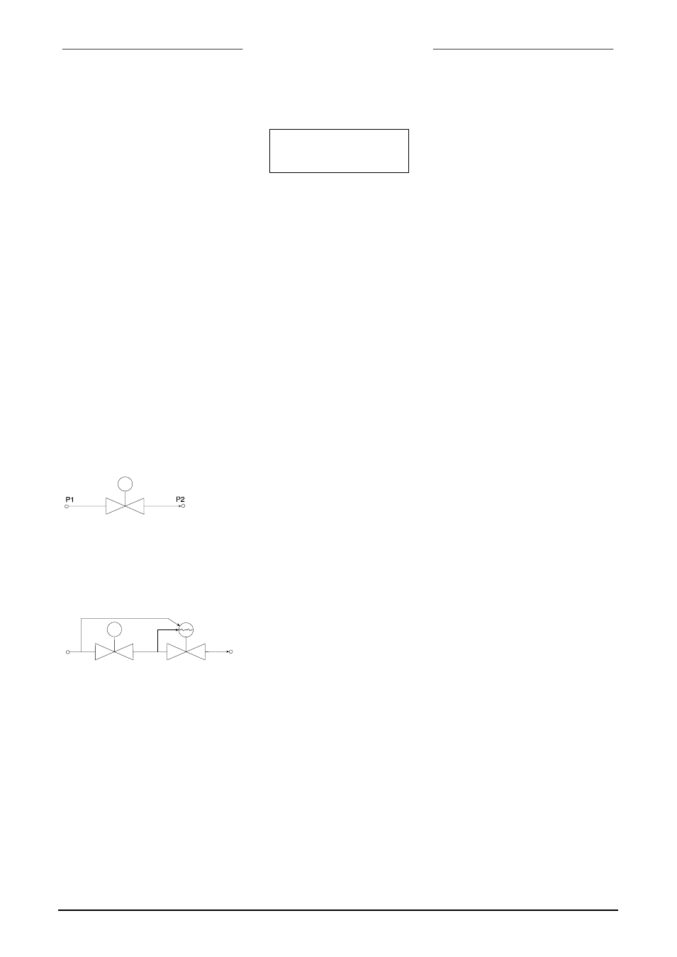
1.5.2 Vary-P valve
For process conditions where up- and downstream pressures vary
much, a special type of valve, VARY-P has been designed. This valve
consists of two valves, a solenoid operated control valve and a fixed
adjusted pressure compensation valve.
9.17.001
page 9