9 example schematics, 1 clock adoption, Example schematics – BECKHOFF ET1200 User Manual
Page 55: Clock adoption, Figure 23: quartz crystal connection, 25 m h z, Et1200, Ethernet phy
Example Schematics
Slave Controller
– ET1200 Hardware Description
III-45
9
Example Schematics
9.1
Clock Adoption
The layout of the clock source has the biggest influence on EMC/EMI of a system design.
Although a clock frequency of 25 MHz requires not extensive design efforts, the following rules shall
help to improve system performance:
Keep clock source and ESC as close as possible close together.
Ground Layer should be seamless in this area.
Power supply should be of low impedance for clock source and ESC clock supply.
Capacitors shall be used as recommended by the clock source component.
Capacities between clock source and ESC clock supply should be in the same size (values
depend upon geometrical form of board).
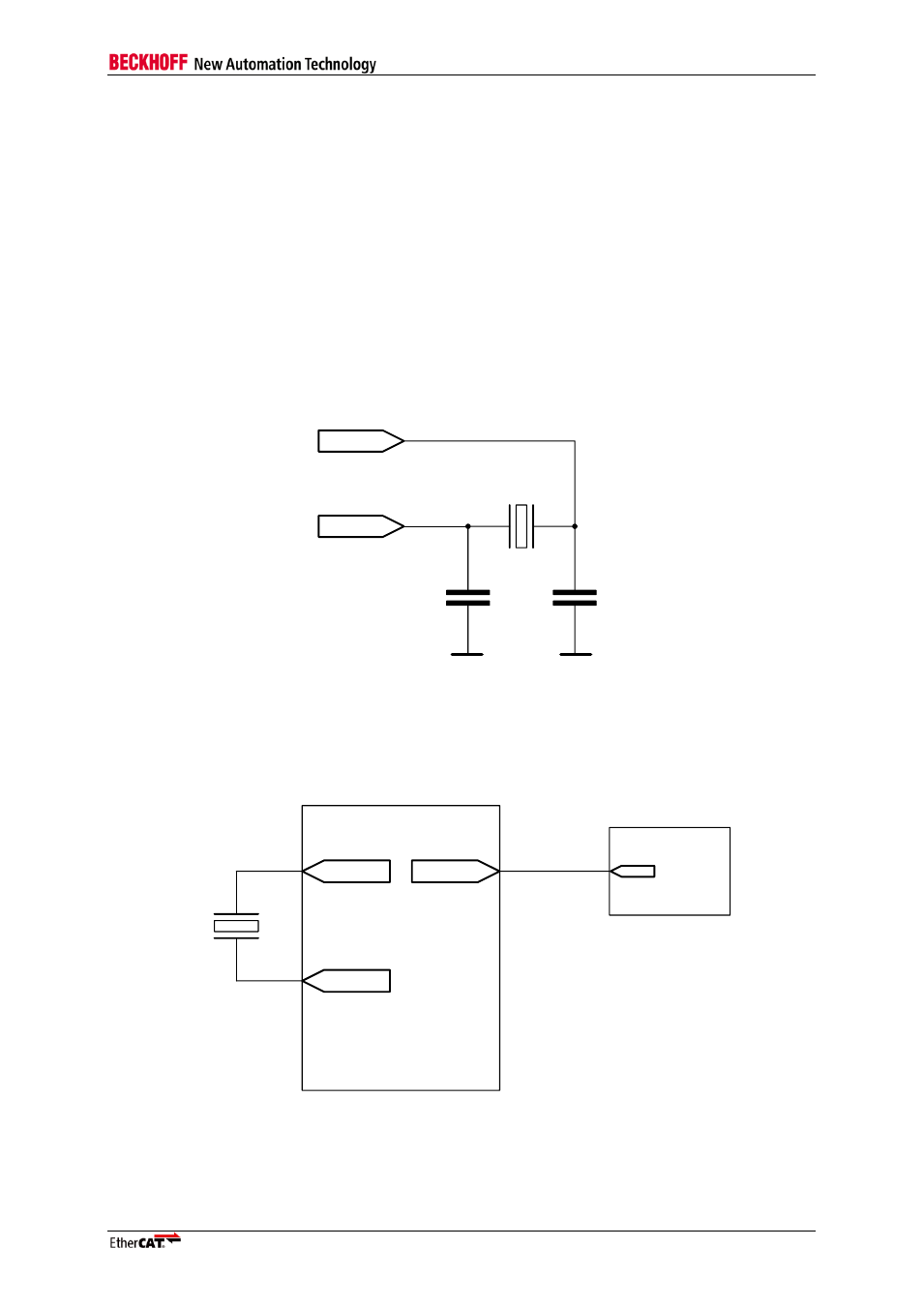
The initial accuracy of the ET1200 clock source has to be 25ppm or better.
OSC_IN
OSC_OUT
25 MHz
GND
PLL
GND
PLL
Figure 23: Quartz crystal connection
NOTE: The value of the load capacitors depends on the load capacitance of the crystal, the pin capacitance C
OSC
of the ESC pins and the board design (typical 12pF each if C
L
= 10pF).
2
5
M
H
z
OSC_OUT
OSC_IN
ET1200
CLK25OUT
Ethernet
PHY
CLK25
Figure 24: Quartz crystal Clock source for ET1200 and Ethernet PHYs