7 physical ports and pdi pins, Physical ports and pdi pins, Table 21: combinations of chip modes and pdis – BECKHOFF ET1200 User Manual
Page 27
Pin Description
Slave Controller
– ET1200 Hardware Description
III-17
3.7
Physical Ports and PDI Pins
The ET1200 pin out is optimized in order to achieve an optimum of size and features. To obtain this,
there is a number of pins where either communication or PDI functionality can be assigned to,
depending on the chip mode. The selected chip mode might reduce PDI possibilities
The ET1200 has 18 PDI pins, PDI[17:0]. They are structured in two groups: PDI[7:0] and PDI[17:8].
PDI[7:0] are always available for PDI signals, PDI[17:8] are available for PDI signals in MODE 00, in
MODE 10/11 they are used for MII signals.
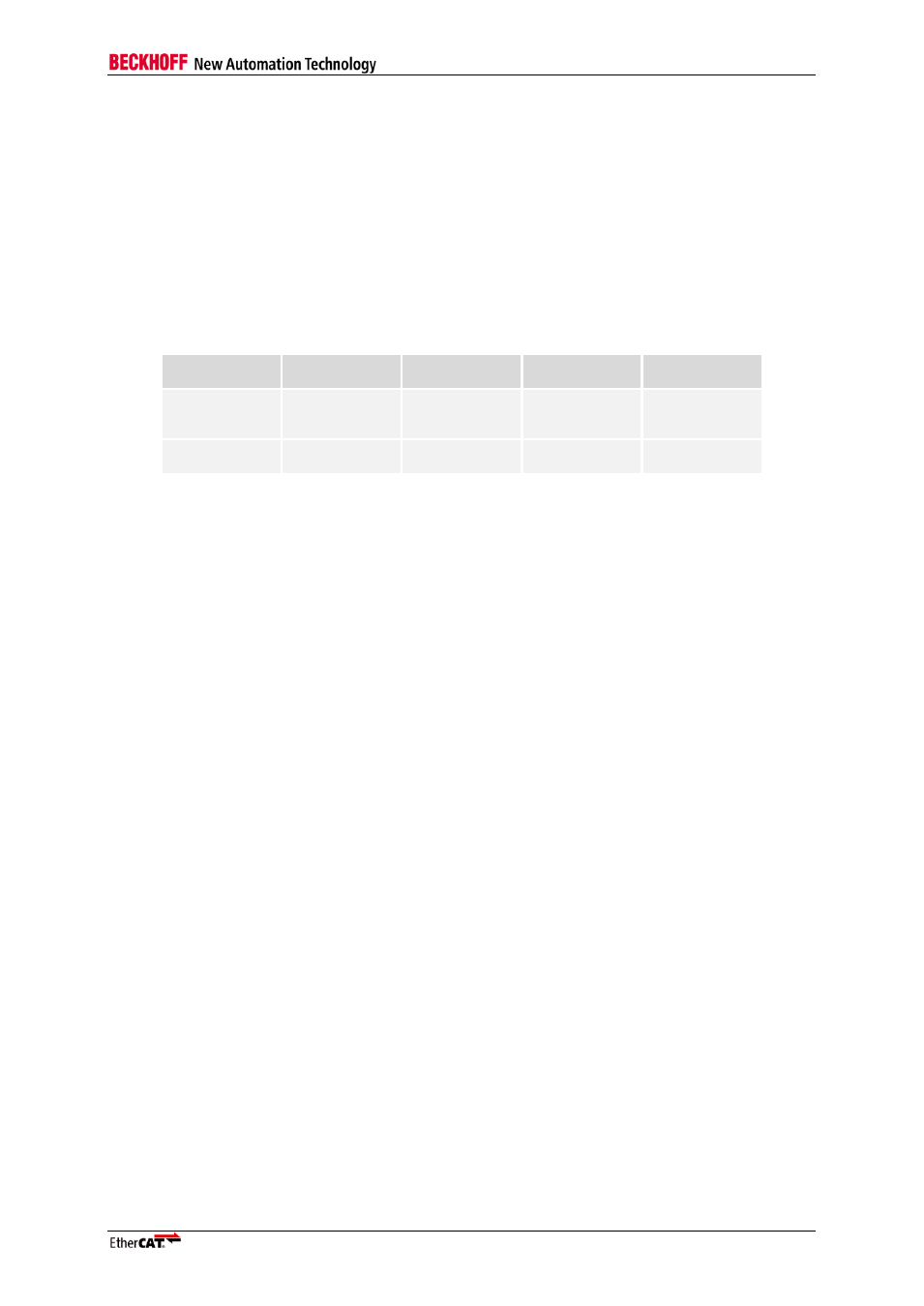
Possible Chip mode / PDI combinations
Table 21: Combinations of Chip modes and PDIs
Chip mode
SPI
Digital I/O
EBUS bridge
(log. port 3)
MII bridge
(log. port 3)
MODE 00
SPI
+12 Bit GPO
16 Bit I/O
+ control/status
signals
EBUS bridge
+12 Bit GPO
MII bridge
+CLK25OUT +1
Bit GPO
MODE 10/11
SPI
+12 Bit GPO
8 Bit I/O
EBUS bridge +2
Bit GPO
Not available