5 pdi[7:0] signals, 8 pdi signal pinout depending on selected pdi, Pdi[7:0] signals – BECKHOFF ET1200 User Manual
Page 30: Pdi signal pinout depending on selected pdi, Table 24: pdi pins
Pin Description
III-20
Slave Controller
– ET1200 Hardware Description
3.7.5
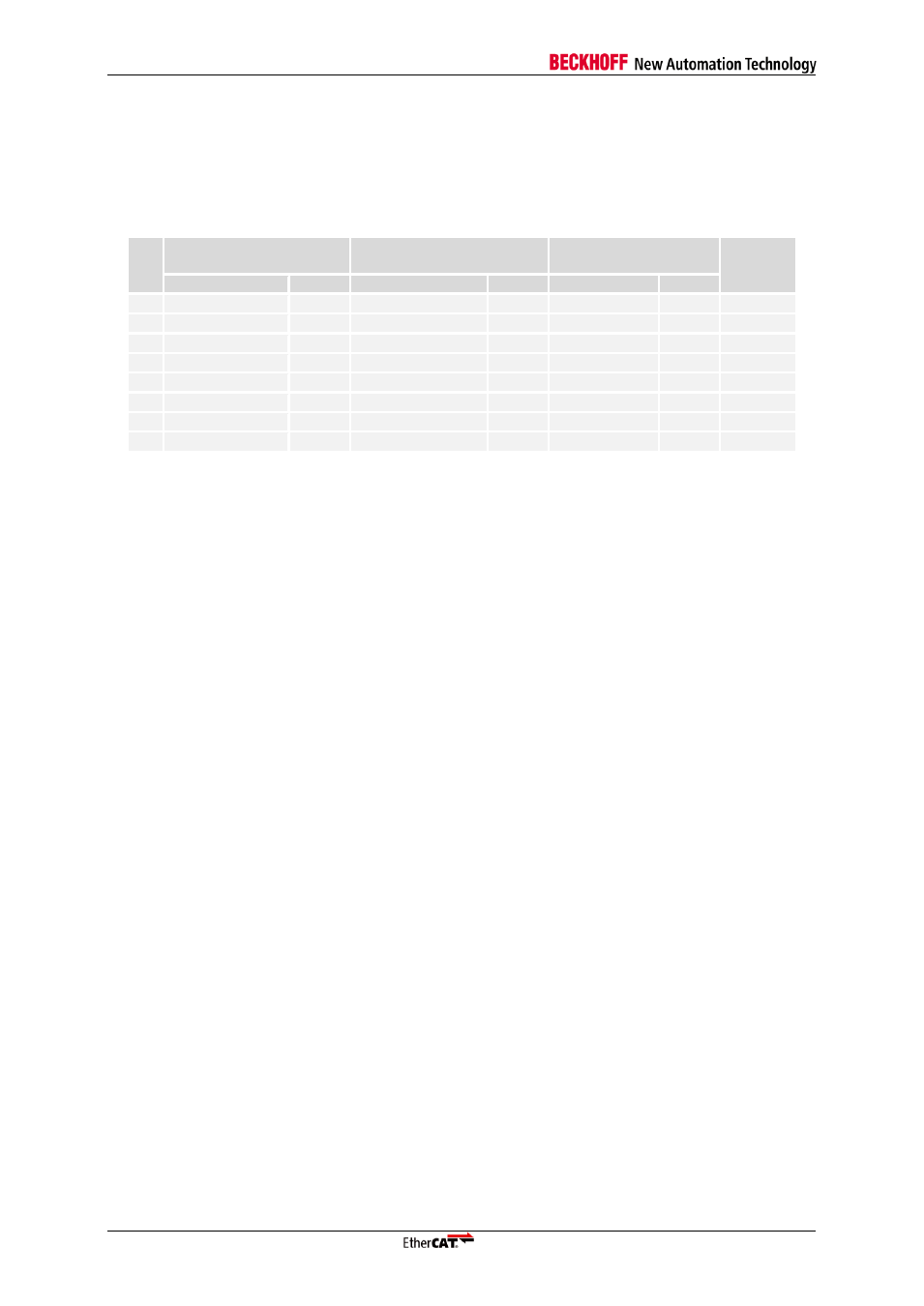
PDI[7:0] Signals
Table 24 shows the PDI[7:0] signals. The direction of all PDI pins depends on the PDI configuration
stored in the SII EEPROM.
Table 24: PDI pins
Pin
Pin
PDI, C25ENA=0,
CLK_MODE=00
PDI, C25ENA=1,
CLK_MODE/=00
Internal
PU/PD
Name
Dir.
Signal
Dir.
Signal
Dir.
46
PDI[0]
BD/LO+
PDI[0]
BD/LO+
PDI[0]
BD/LO+
45
PDI[1]
BD/LO-
PDI[1]
BD/LO-
PDI[1]
BD/LO-
44
PDI[2]
BD/LI+
PDI[2]
BD/LI+
PDI[2]
BD/LI+
27 k
Ω PD
43
PDI[3]
BD/LI-
PDI[3]
BD/LI-
PDI[3]
BD/LI-
27 k
Ω PU
40
PDI[4]
BD
PDI[4]
BD
PDI[4]
BD
39
PDI[5]
BD
PDI[5]
BD
PDI[5]
BD
38
PDI[6]/CLK25OUT
BD
PDI[6]
BD
CLK25OUT
O
37
PDI[7]/CPU_CLK
BD
PDI[7]
BD
CPU_CLK
O
3.8
PDI Signal Pinout depending on selected PDI
The PDI signal pinout depends on the selected PDI (SII EEPROM). The PDI selection and PDI signal
pinout is subject to restrictions introduced by the port configuration. Digital I/O and SPI PDI are
available in any configuration
– although the I/O width can be reduced depending on the configuration.
The MII bridge port PDIs is only available in chip mode 00.
Refer to PDI descriptions for further PDI and PDI signal descriptions.
The SPI PDI supports additional general purpose output signals, which are not part of the SPI PDI
description:
GPO[x]
General purpose output signals.