BECKHOFF ET1200 User Manual
Page 4
DOCUMENT HISTORY
III-IV
Slave Controller
– ET1200 Hardware Description
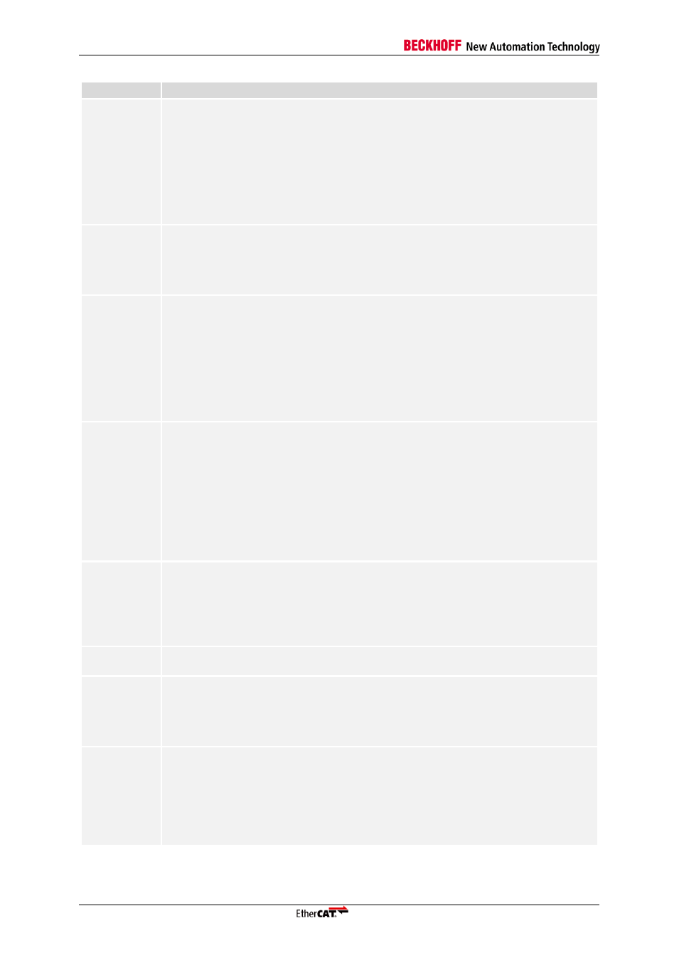
Version
Comment
1.1
Clarified I/O voltage with respect to I/O power supply (only 3.3V I/O with
V
CCI/O
=3.3V, and no 5V input tolerance unless V
CCI/O
=5V)
Update to ET1200 stepping 1
Added/revised OSC_IN, CLK25OUT, and MII TX signal timings
Added soldering profile
PHY address configuration changed
Added feature detail overview, removed redundant feature details
PDI and DC SYNC/LATCH signals are not driven until EEPROM is loaded
Editorial changes
1.2
PHY address configuration chapter added, configuration revised
Enhanced link detection for MII available depending on PHY address
configuration
Ethernet Management Interface: read and write times were interchanged
Editorial changes
1.3
Added reset timing figure and power-on value sample time
Direction of Distributed Clocks SYNC/LATCH signals is configurable
Information on CLK25OUT/CPU_CLK clock output during reset added
Description of internal PU/PD resistors at EBUS_RX pins enhanced
Power supply example schematic clarified
Enhanced package information: MSL and plating material
Digital I/O PDI: added SOF/OUTVALID description
SPI PDI: Read busy signaling not recommended
Editorial changes
1.4
OSC_IN/OSC_OUT pin capacitance added, crystal connection note extended
Release Notes added
Input threshold voltage for OSC_IN added
Renamed Err(x) LED to PERR(x)
Digital I/O PDI: OE_CONF functionality in bidirectional mode corrected
Digital I/O PDI: output event description corrected (EOF mode and WD_TRIG
mode)
SPI PDI: access error if SPI_DI not 1 in the last read byte (not SPI_DO)
AC timing: forwarding delay figures added
Editorial changes
1.5
AC timing: forwarding delay figures MII to MII added
Reset timing figure corrected
Maximum soldering profile added
SPI PDI updated
SII EEPROM interface is a point-to-point connection
Editorial changes
1.6
Update to ET1200-0002
Editorial changes
1.7
Enhanced Link Detection must not be activated if EBUS ports are used
Enhanced Link Detection for MII ports requires PHY address offset = 0
Digital Output principle schematic updated
Chip label updated
Editorial changes
1.8
Update to ET1200-0003
Enhanced Link Detection for MII ports supports PHY address offset 0 and 16
Enhanced Link Detection for MII ports can be disabled at any time
Enhanced Link Detection for EBUS ports is always disabled
MII management interface issues additional MCLK cycle after write accesses
Remote link down signalling time configurable 0x0100[22]
Editorial changes