2 digital i/o interface, 1 interface, 2 configuration – BECKHOFF ET1200 User Manual
Page 40: 3 digital inputs, Digital i/o interface, Interface, Configuration, Digital inputs, Table 36: et1200 digital i/o signals, Figure 7: et1200 digital i/o signals
PDI Description
III-30
Slave Controller
– ET1200 Hardware Description
6.2
Digital I/O Interface
6.2.1
Interface
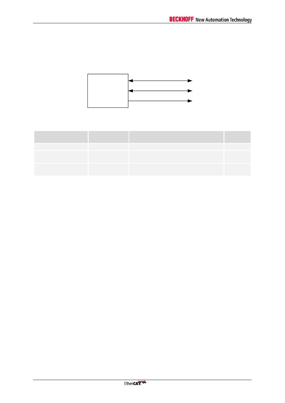
The Digital I/O PDI is selected with PDI type 0x04. The signals of the Digital I/O interface are:
ET1200
I/O[15:0]
LATCH_IN/SOF
OUTVALID/WD_TRIG
Figure 7: ET1200 Digital I/O Signals
Table 36: ET1200 Digital I/O signals
Signal
Direction
Description
Signal
polarity
I/O[15:0]
IN/OUT/BIDIR
Input/Output or Bidirectional data
LATCH_IN/SOF
IN/OUT
External data latch signal or Start of
Frame
act. high
OUTVALID/WD_TRIG
OUT
Output data is valid/Output event or
Watchdog Trigger
act. high
NOTE: Unsupported control signals OE_EXT and OE_CONF are assumed to be high.
6.2.2
Configuration
The Digital I/O interface is selected with PDI type 0x04 in the PDI control register 0x0140. It supports
different configurations, which are located in registers 0x0150
– 0x0153.
6.2.3
Digital Inputs
Digital input values appear in the process memory at address 0x1000:0x1003. EtherCAT devices use
Little Endian byte ordering, so I/O[7:0] can be read at 0x1000 etc. Digital inputs are written to the
process memory by the Digital I/O PDI using standard PDI write operations.
Digital inputs can be configured to be sampled by the ESC in four ways:
Digital inputs are sampled at the start of each Ethernet frame, so that EtherCAT read commands
to address 0x1000:0x1003 will present digital input values sampled at the start of the same frame.
The SOF signal can be used externally to update the input data, because the SOF is signaled
before input data is sampled.
The sample time can be controlled externally by using the LATCH_IN signal. The input data is
sampled by the ESC each time a rising edge of LATCH_IN is recognized.
Digital inputs are sampled at Distributed Clocks SYNC0 events.
Digital inputs are sampled at Distributed Clocks SYNC1 events.
For Distributed Clock SYNC input, SYNC generation must be activated (register 0x0981). SYNC
output is not necessary (register 0x0151). SYNC pulse length (registers 0x0982:0x0983) should not be
set to 0, because acknowledging of SYNC events is not possible with Digital I/O PDI. Sample time is
the beginning of the SYNC event.