2 syncsignals and latchsignals, 1 interface, 2 configuration – BECKHOFF EtherCAT Technology Section I User Manual
Page 80: Syncsignals and latchsignals, Interface, Configuration, Table 31: distributed clocks signals, Figure 29: distributed clocks signals
Distributed Clocks
I-60
Slave Controller
– Technology
9.2
SyncSignals and LatchSignals
ESCs with Distributed Clocks support generation of SyncSignals and time stamping of LatchSignals.
The SyncSignals can be used internally for
Interrupt generation (mapping to AL Event Request register 0x0220:0x0223 and PDI IRQ)
PDI Digital Output Update events
PDI Digital Input Latch events
The SyncSignals can also be directly mapped to output signals (SYNC[1:0]) for use by external
devices, e.g., as interrupt signals (less jitter than PDI IRQ, no interrupt source decoding).
The Latch Event unit supports time stamping of up to two LatchSignals (LATCH[1:0], rising and falling
edge separately), and time stamping of SyncManager events for debugging purposes.
9.2.1
Interface
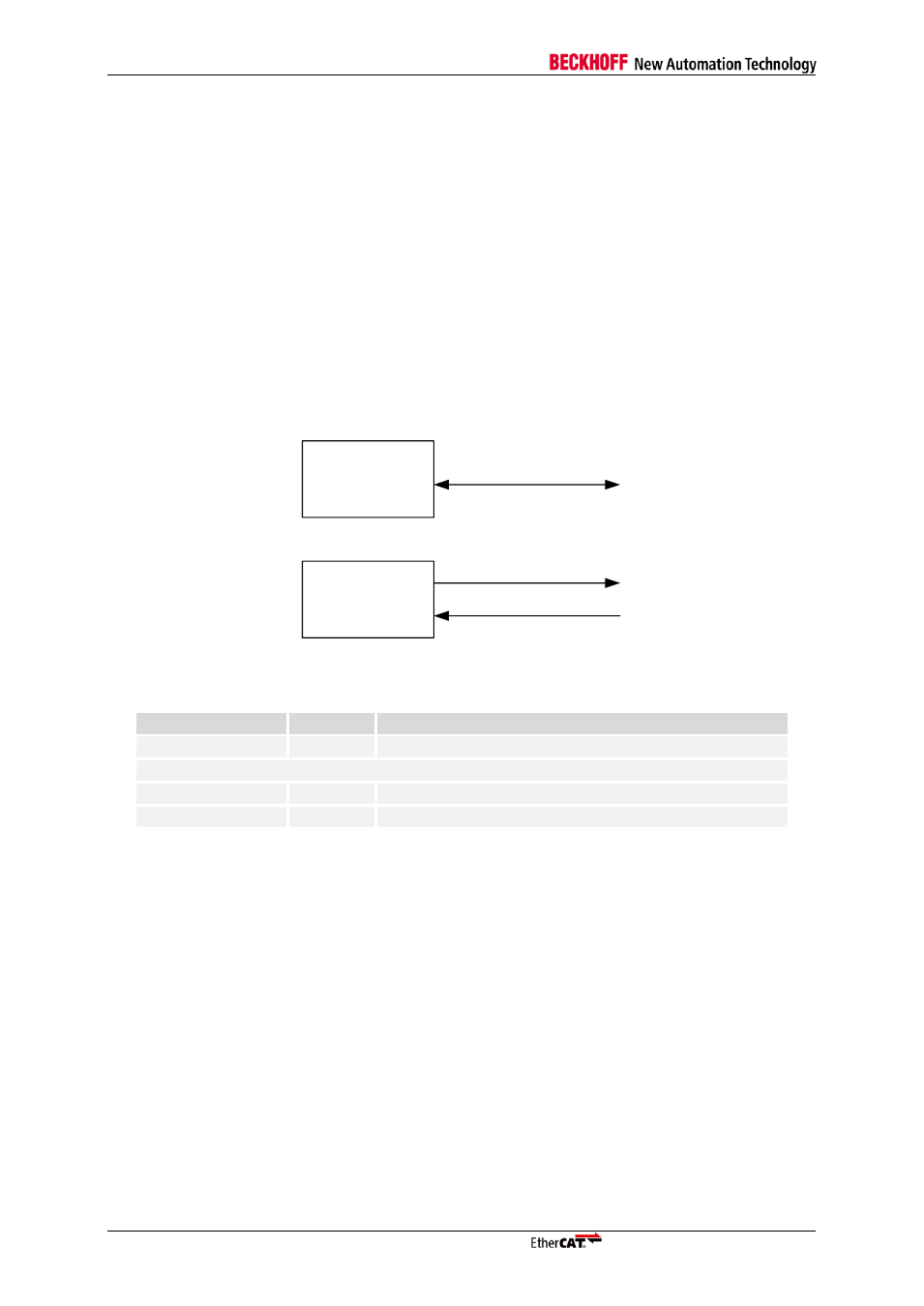
The Distributed Clocks unit has the following external signals (depending on the ESC and the ESC
configuration):
EtherCAT
device
LATCH[1:0]
SYNC[1:0]
EtherCAT
device
SYNC/LATCH[1:0]
or
Figure 29: Distributed Clocks signals
Table 31: Distributed Clocks signals
Signal
Direction
Description
SYNC/LATCH[1:0]
IN/OUT
Combined SyncSignals / LatchSignals
or (ESC dependent)
SYNC[1:0]
OUT
SyncSignals (also named SYNC0/SYNC1)
LATCH[1:0]
IN
LatchSignals (also named LATCH0/LATCH1)
Not all of these signals might be available depending on the ESC and its hardware configuration.
9.2.2
Configuration
The mapping of Distributed Clocks SyncSignals and LatchSignals to the external SYNC/LATCH[1:0]
signals is controlled by the setting of the Sync/Latch PDI Configuration register 0x0151. The
SYNC[1:0] driver characteristics are also selected in this register. The SyncSignals are internally
available for interrupt generation and Digital I/O synchronization regardless of the Sync/Latch PDI
Configuration. The mapping of SyncSignals to the AL Event Request register is also controlled by the
Sync/Latch PDI Configuration register 0x0151.
The length of a SyncSignal pulse is defined in the DC Pulse Length of SYNC Signals register
(0x0982:0x0983). A value of 0 selects acknowledged modes.
Some ESCs support power saving options (partly disabling DC units) controlled by two bits of the ESC
Configuration register (0x0141[3:2]), others have individual configuration options for each
SyncSignal/LatchSignal.
The Sync/Latch signals are not driven (high-impedance) by some ESCs until the SII EEPROM is
successfully loaded. Refer to Section III for details. Take care of proper SyncSignal usage while the
EEPROM is not loaded (e.g. pull-down/pull-up resistors).