1 clock synchronization process, Clock synchronization process, Reference clock slave clock t – BECKHOFF EtherCAT Technology Section I User Manual
Page 69: System time < local time system time > local time
Distributed Clocks
Slave Controller
– Technology
I-49
9.1.1
Clock Synchronization Process
The clock synchronization process consists of three steps:
1. Propagation Delay Measurement:
The master initiates propagation delay measurement between all slaves in all directions. Each
EtherCAT slave controller measures the receive time of the measurement frame. The master
collects the time stamps afterwards and calculates the propagation delays between all slaves.
2. Offset compensation to Reference Clock (System Time):
The local time of each slave clock is compared to the System Time. The difference is
compensated individually by writing it to each slave. All devices get the same absolute System
Time.
3. Resetting the Time Control Loop:
The current filter status needs to be reset to eliminate influences of previous measurements and
improve repeatability.
4. Drift compensation to Reference Clock:
The drift between Reference Clock and local clock has to be compensated by regularly measuring
the differences and readjusting the local clocks.
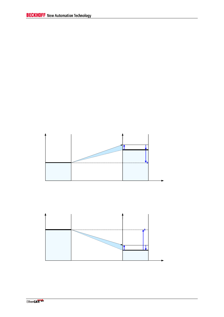
The following figure illustrates the compensation calculations for two cases, in the first case the
System Time is less than the
slave’s local time, in the second case, it is the other way around.
Reference
Clock
Slave Clock
t
System Time
t
Local time
Drif
t co
mpe
nsa
tion
fra
me
carr
ying
cur
ren
t Sy
stem
Tim
e
TX
Propagation delay compensation
Offset compensation
Drift compensation
Reference
Clock
Slave Clock
t
System Time
t
Local Time
Drift c
ompe
nsatio
n fra
me
carry
ing c
urren
t Sys
tem T
ime
TX
Propagation delay compensation
Offset compensation
RX
Drift compensation
RX
Goal: Slave clock has
copy of System Time
System Time < Local Time
System Time > Local Time
Prop
agat
ion d
elay
Propa
gation
delay
System Time
Local time
System Time
Local time
Goal: Slave clock has
copy of System Time
x
x
Figure 27: Propagation Delay, Offset, and Drift Compensation