6 ebus/lvds physical layer, 1 interface, Ebus/lvds physical layer – BECKHOFF EtherCAT Technology Section I User Manual
Page 55: Interface, Table 20: ebus interface signals, Figure 16: ebus interface signals
EBUS/LVDS Physical Layer
Slave Controller
– Technology
I-35
6
EBUS/LVDS Physical Layer
EBUS is an EtherCAT Physical Layer designed to reduce components and costs. It also reduces
delay inside the ESC. The EBUS physical layer uses Low Voltage Differential Signaling (LVDS)
according to the ANSI/TIA/EIA-
644 “Electrical Characteristics of Low Voltage Differential Signaling
(LVDS) Interface Circuits” standard.
EBUS has a data rate of 100 Mbit/s to accomplish the Fast Ethernet data rate. The EBUS protocol
simply encapsulates Ethernet Frames, thus EBUS can carry any Ethernet frame
– not only EtherCAT
frames.
EBUS is intended to be used as a backplane bus, it is not qualified for wire connections.
6.1
Interface
Two LVDS signal pairs per EBUS link are used, one for reception and one for transmission of
Ethernet/EtherCAT frames.
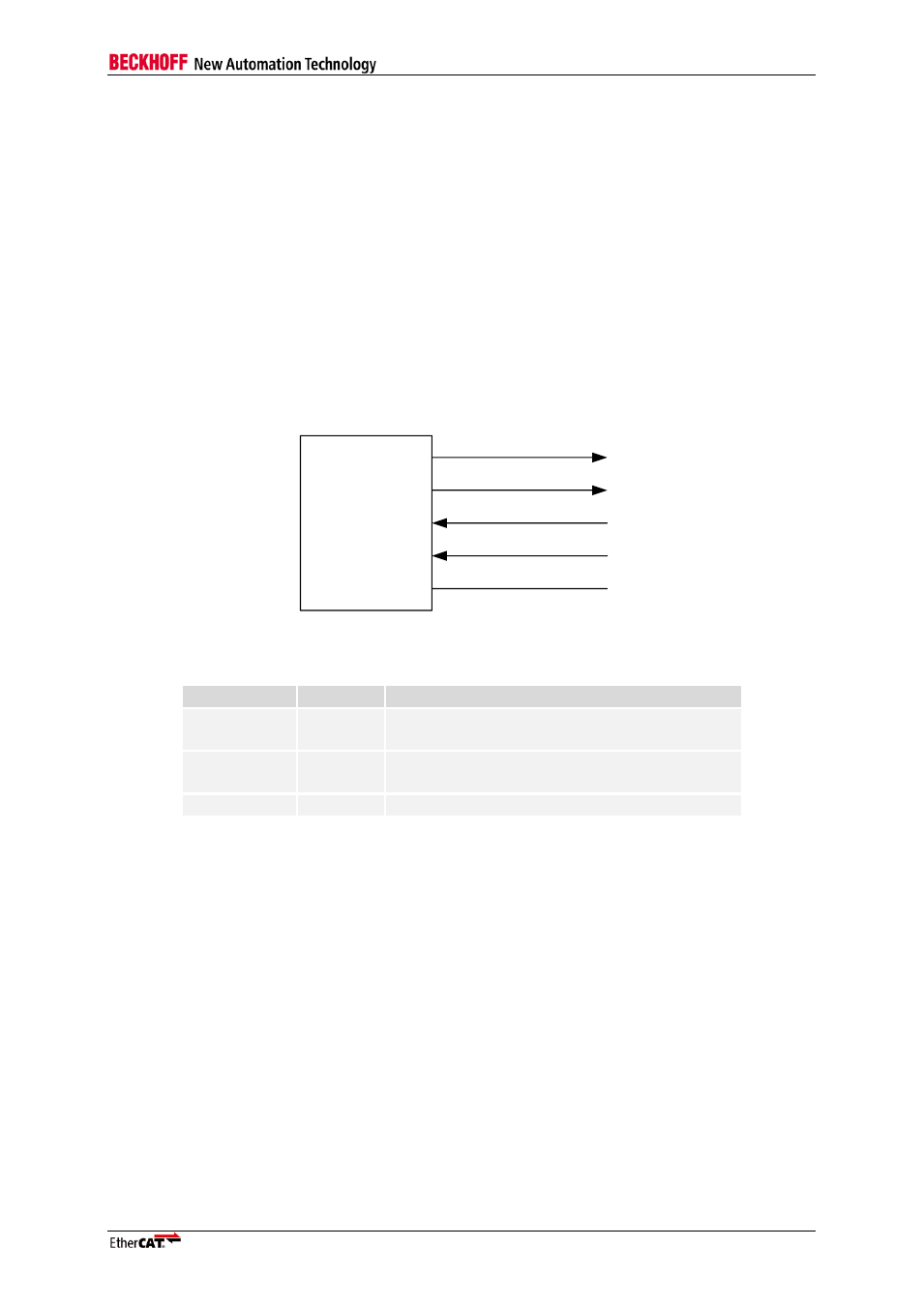
The EBUS interface has the following signals:
EtherCAT
device
EBUS-TX-
EBUS-TX+
EBUS-RX+
EBUS-RX-
RBIAS
Figure 16: EBUS Interface Signals
Table 20: EBUS Interface signals
Signal
Direction
Description
EBUS-TX+
EBUS-TX-
OUT
EBUS/LVDS transmit signals
EBUS-RX+
EBUS-RX-
IN
EBUS/LVDS receive signals
RBIAS
BIAS resistor for EBUS-TX current adjustment
Unused EBUS ports can be left unconnected, only the LVDS termination resistor and the RBIAS
resistor are mandatory.