Remote sensing -25, Figure 3-22. remote voltage sensing network -25, N 3.9 – AMETEK SGA Series User Manual
Page 75: Power supply, Remote sensing
Sorensen SGA Series
Operation
M550129-01 Rev AG
3-25
3.9
REMOTE SENSING
Remote voltage sensing is recommended at all times, whether the sense
leads are connected to the load or to the output terminals. Remote sensing is
required to meet the performance specifications of the power supply. It is
essential in applications where the load is located some distance from the
power supply, or the voltage drop of the power output leads significantly
interferes with load regulation.
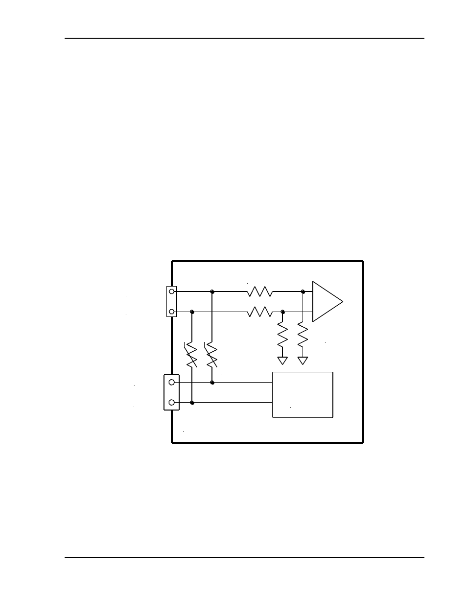
The voltage accuracy specifications are valid only with remote sense
connected. Disconnecting the remote sense leads will introduce an error, with
the output voltage increasing. The error occurs because an additional
resistance (PTC local resistor network in Figure 3-22) is present in the circuit
of the resistor divider for voltage sensing, to provide the default local sensing
of the output voltage at the output terminals. When remote sense is
connected, the PTC local resistor network is short-circuited, effectively
removing it from the circuit.
Sense (+)
Power Supply
Out (+)
Out (-)
Sense (-)
Remote Sense
Resistor Network
Output
Power
Converter
PTC
Local
Resistor
Network
Remote
Sense
Amplifier
Figure 3-22. Remote Voltage Sensing Network