Table 3, Ee table 3, O table 3 – AMETEK SGA Series User Manual
Page 67
Sorensen SGA Series
Operation
M550129-01 Rev AG
3-17
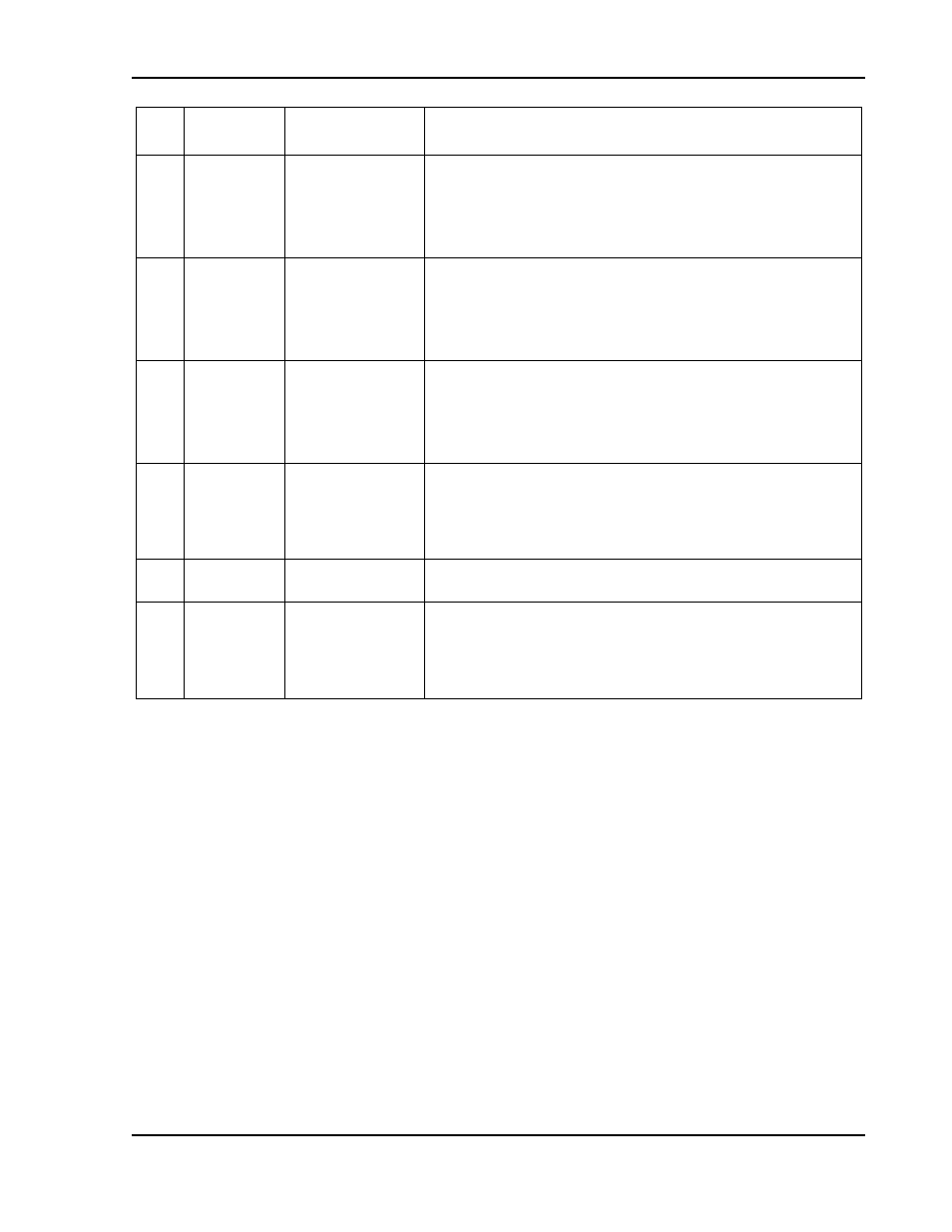
Pin
Reference
Electrical
Parameters
Functional Description
20
VP RTN
Zin ~ 10 k
Voltage programming signal return to be used with Pins J1-9,
J1-15 or J1-21; also must be externally connected to Pin J1-6
(COM) signal return when voltage programming is utilized.
Circuit is electrically connected to the output power negative
terminal.
21
VP RES
*
1mA current
source with
compliance
voltage of
~ 10.8 V
Current source of 1 mA for remote voltage programming
using a resistance connected to signal return
Pin J1-4 or Pin J1-20 (VP RTN): 0-5 k
Ω = 0-100% of full-
scale output voltage. Circuit is electrically connected to the
output power negative terminal. See Section 3.6.
22
IP RES
*
1mA current
source with
compliance
voltage of
~ 10.8 V
Current source of 1 mA for remote current programming
using a resistance connected to signal return
Pin J1-23 or Pin J1-25 (IP RTN): 0- 5 k
Ω = 0-100% of full-
scale output current. Circuit is electrically connected to the
output power negative terminal. See Section 3.5.
23
IP RTN
Zin ~ 10 k
Current programming signal return which is to be used with
Pins J1-10, J1-16 or J1-22; also must be externally
connected to Pin J1-6 (COM) signal return when current
programming is utilized. Circuit is electrically connected to the
output power negative terminal.
24
COM
†
—
Signal return. Internally connected to Pin J1-6. Circuit is
electrically connected to the output power negative terminal.
25
IP RTN
Zin ~ 10 k
Current programming signal return which is to be used with
Pins J1-10, J1-16 or J1-22; also must be externally
connected to Pin J1-6 (COM) signal return when current
programming is utilized. Circuit is electrically connected to the
output power negative terminal.
†
With the option, Remote Isolated Analog Interface control, the control signal return is isolated from the
output power negative terminal. See Section 1.2.2 and Section 3.10.
*
Signals not available with the option, Remote Isolated Analog Interface control.
Table 3
–5. Analog Control Connector (J1), Designations and Functions