AGI Security SYS-16HN44P User Manual
Page 61
49
Figure 2-24
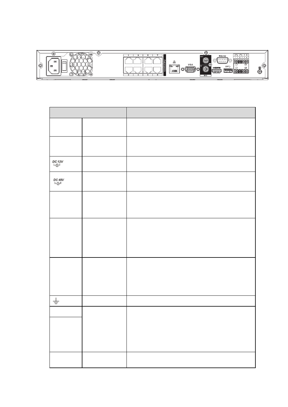
The NVR42-8P series rear panel is shown as below. See Figure 2-25.
Figure 2-25
Please refer to the following sheet for detailed information.
Name
Function
Power
switch
/
Power on/off button.
Power input
socket
/
Input AC 100~240V.
For NVR42-8P series product only.
Power input port
Input DC 12V/5A.
For NVR42 series product only.
Power input port
Switch power port. Input DC 48//1.04A.
For NVR42-P series product only.
MIC IN
Audio input port
Bidirectional talk input port. It is to receive the analog
audio signal output from the devices such as
microphone, pickup.
MIC OUT
Audio output port Audio output port. It is to output the analog audio signal
to the devices such as the sound box.
Bidirectional talk output.
Audio output on 1-window video monitor.
Audio output on 1-window video playback.
1~4
Alarm input port
1~4
There are two types; NO (normal open)/NC
(normal close).
When your alarm input device is using external
power, please make sure the device and the NVR
have the same ground.
GND
Alarm input ground port.
N1, N2
Alarm output port
1~2
2 groups of alarm output ports. (Group 1:port
NO1~C1,Group 2:port NO2~C2).Output alarm
signal to the alarm device. Please make sure there
is power to the external alarm device.
NO:Normal open alarm output port.
C:Alarm output public end.
C1, C2
A
RS-485
communication
RS485_A port. It is the cable A. You can connect to the
control devices such as speed dome PTZ.