Digital i/o cable installation, Digital i/o cable wiring assignments, Figure 2-9. dio cable – Adept AnyFeeder User Manual
Page 27
Installing Cables and Power
Adept AnyFeeder User’s Guide, Rev. B
27
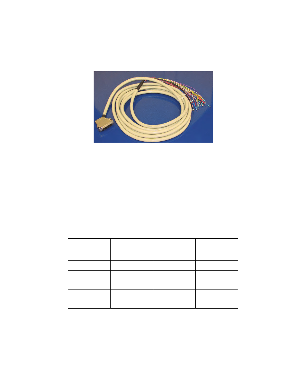
Digital I/O Cable Installation
A digital I/O cable is supplied with the Adept AnyFeeder (see
). Connect the
female end of the cable to the parallel I/O +24 VDC in I/O Pwr (J3) port on the Adept
AnyFeeder.
Figure 2-9. DIO Cable
Digital I/O Cable Wiring Assignments
The supplied digital I/O cable must be wired as shown in
.
NOTE: If you want to communicate with your Adept AnyFeeder using
digital I/O rather than serial communications, refer to
cable pin/wire assignments.
NOTE: Regardless of your method of communicating with the Adept
AnyFeeder (DIO or RS232 Serial), you must supply power to the logic
board through this cable on the pins specified in
Table 2-2: Digital I/O Wiring Assignments
Function
Pin #
DSUB 25
Wire Color
Power Supply
Robot
Controller
+24 VDV
25
WH / BK
+24 VDC
+24 VDC
13
WH / GN
+24 VDC
0 VDC
24
BN / RD
0 VDC
0 VDC
12
RD / BU
0 VDC
Shield
N/A
BK
Ground to Case