Zilog EZ80F91 User Manual
Page 55
eZ80F91 Development Kit
User Manual
UM014220-0508
eZ80F91 Module
50
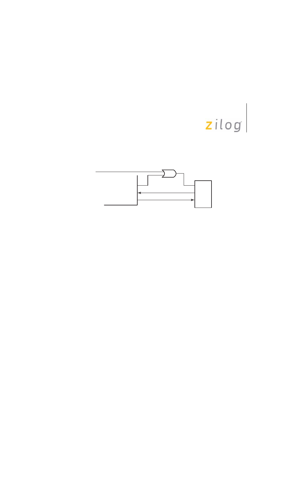
displays the eZ80F91 Module IrDA hardware connections.
The eZ80F91 Module features an Infrared Encoder/Decoder register that
configures the IrDA function. This register is located at address
0BFh
in
the internal I/O register map.
The Infrared Encoder/Decoder register contains three control bits. Bit 0
enables or disables the IrDA encoder/decoder block. Bit 1, if it is set,
enables received data to pass into the UART0 Receive FIFO data buffer.
Bit 2 is a test function that provides a loopback sequence from the TxD
pin to the RxD input.
Bit 1, the Receive Enable bit, is used to block data from filling up the
Receive FIFO when the eZ80F91 Module is transmitting data. Because
IrDA signal passes through the air as its transmission medium, transmit-
ted data can also be received. This Receive Enable bit prevents this data
from being received. After the eZ80F91 Module completes transmitting,
this bit is changed to allow for incoming messages.
The code that follows provides an example of how this function is
enabled on the eZ80F91 Module.
Figure 15. IrDA Hardware Connections
External Disable
eZ80F91
Device
IrDA
PD2(IR_SD)
PD1(RxD)
PD0(TxD)
SD
RD
TD